
Feed-throughs for high external pressure applications and method for producing same

a high external pressure and feed-through technology, applied in the direction of lead-in/lead-through insulators, fuel cell auxiliaries, fuel cell manufacturing, etc., can solve the problems of complex routing geometry of conductors, many times more space consuming than would be necessary, and achieves reduced tendency for spontaneous breakage of insulating materials, high pressure resistance, and reduced production costs

Active Publication Date: 2020-07-28
SCHOTT AG
View PDF24 Cites 0 Cited by
  • Summary
  • Abstract
  • Description
  • Claims
  • Application Information

AI Technical Summary

Benefits of technology

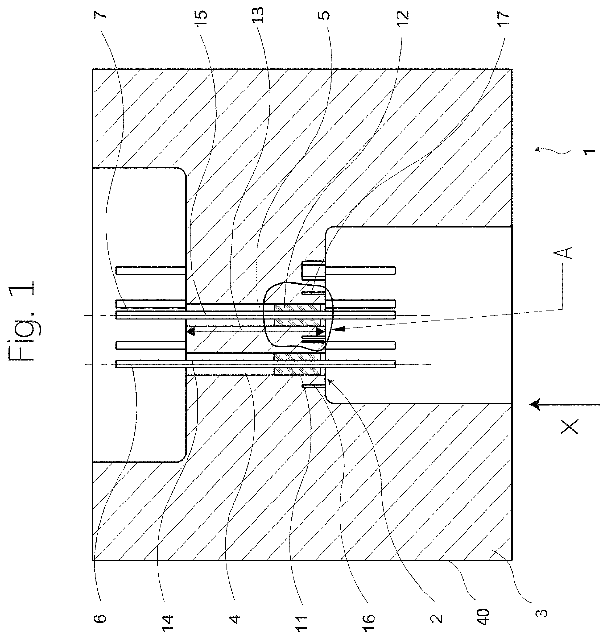
[0016]The invention intends to provide feed-throughs which are capable of reliably holding also individual functional elements, such as functional elements comprising conductors, and this in a simple and fluid-tight manner during long-term operation and even under high pressures. In the context of the present disclosure, high pressures in particular refer to pressures of more than 1000 bar, advantageously in particular even pressures of more than 1500 bar or more than 2000 bar. Furthermore, it would be advantageous to avoid complex routing geometries, for example for functional elements that comprise conductors. It would also be advantageous to avoid space-consuming geometries and to allow to arrange a plurality of functional elements next to each other in the feed-through.
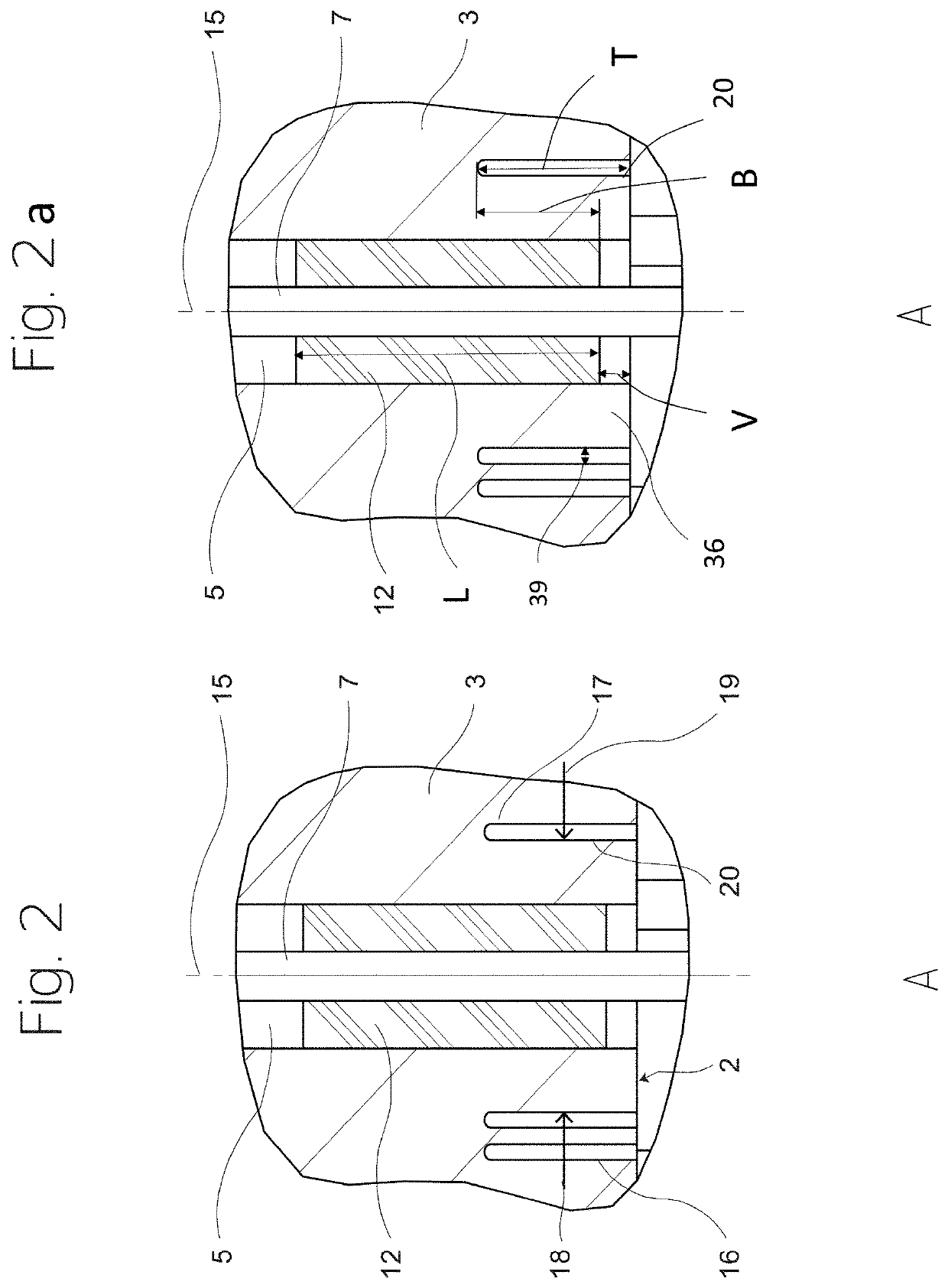
[0042]A compression glass seal is obtained if the thermal expansion coefficient of the material of the base body is greater than that of the material of the insulating material fused into the through-hole. In conventional compression glass fabrication, the thermal expansion coefficient of the functional element is equal to or smaller than the thermal expansion coefficient of the insulating material. Although a slightly higher thermal expansion is also possible, however, it might reduce the pressure in the glass seal which is exerted by the insulating material to the functional element in the radial direction, and thus the pressure resistance and squeeze-out resistance. With the groove or the protruding portion, it is now also possible to use a higher expansion material for the functional element, since the additional pressure is passed through the insulating material to the functional element, and, thus, the feed-through of the invention is nevertheless suitable for higher pressures, despite the mismatch that would exist for conventional embodiments.
[0048]In a method for producing a feed-through, in particular for high external pressure applications, a pressure compensator is formed on a base body of the feed-through, which increases the pressure resistance of the feed-through, and for forming the pressure compensator, material of the base body is reduced in the vicinity of the through-hole on the side of the base body facing the pressure.
[0050]The feed-through of the invention has further advantages in its application in addition to the surprisingly high pressure resistance. Comparative tests with feed-throughs without pressure compensator and with conical or step-like profiles of the through-hole, which represent retaining means for the insulating material, have shown that the feed-throughs according to the invention with pressure compensator exhibit a lower tendency for spontaneous breaks of the insulating material. In the event of such spontaneous breaks, the insulating material is destroyed when a pressure limit is reached, and will burst out of the through-hole. In tests, this burst pressure is measured on a multitude of components, and the result is a Gaussian distribution with a distribution width around a mean value of the burst pressure. Compared with feed-throughs having retaining means, the feed-throughs with pressure compensator according to the invention exhibit a significantly smaller distribution width around the mean value. This means that a smaller safety margin to the required pressure tightness has to be considered in the configurational design of a feed-through according to the invention. Moreover, fewer spontaneous failures are to be expected during operation of a feed-through according to the invention, which improves long-term operation stability and reliability thereof, even in rough application environments.

Problems solved by technology

A drawback of this feed-through is that the forces resulting from the application of pressure are directed through the insulating material surrounding the respective conductor, and that compensation can be achieved only in pairs, with two conductors in each case.
Furthermore, in this arrangement, the respective conductors are routed with a bent about 90° in a housing opening, which not only makes manufacturing difficult, but also complicates the routing geometry of the conductors.
In addition, the geometric dimensions are many times more space consuming than would be necessary if the conductors would be routed straightly.
Due to the necessarily given deformability of the annular recess, the latter is not suitable for use under high external pressures.
Since compression glass seal connections are arranged radially one behind the other with respect to an axial center line of this feed-through, this groove cannot be effective as a pressure compensator and thus does not improve pressure resistance of this feed-through to high external pressures.
This feed-through is not capable of withstanding high pressures.
Such feed-throughs are usually not appropriate to withstand high external pressures, in particular pressures of more than 1000 bar, since the outer flange is often weakened in such cases without however compensating for an elevated external pressure.
However, high pressure resistance is at the expense of the pressure strength or squeeze-out resistance of the insulating material towards lower pressures.
In the event of such spontaneous breaks, the insulating material is destroyed when a pressure limit is reached, and will burst out of the through-hole.
In the case of brittle insulating materials, in particular glass materials and / or at least partially crystalline materials in the through-hole, breakage thereof is usually initiated by formation of an initial crack which propagates further in the insulating material.
The initial crack can be induced by anisotropies and / or defects in the volume of the insulating material, but in particular by defects and / or damage at the surface thereof.
In particular surface damage may arise during operation by interaction with the fluid and / or foreign matter, and may be unavoidable under certain circumstances.

Method used


Image

  • Feed-throughs for high external pressure applications and method for producing same
  • Feed-throughs for high external pressure applications and method for producing same
  • Feed-throughs for high external pressure applications and method for producing same

Examples


Embodiment Construction

[0073]In the following detailed description of the preferred embodiments, the same reference numerals designate the same functional elements, respectively, and the views are not always drawn to scale, for the sake of clarity.

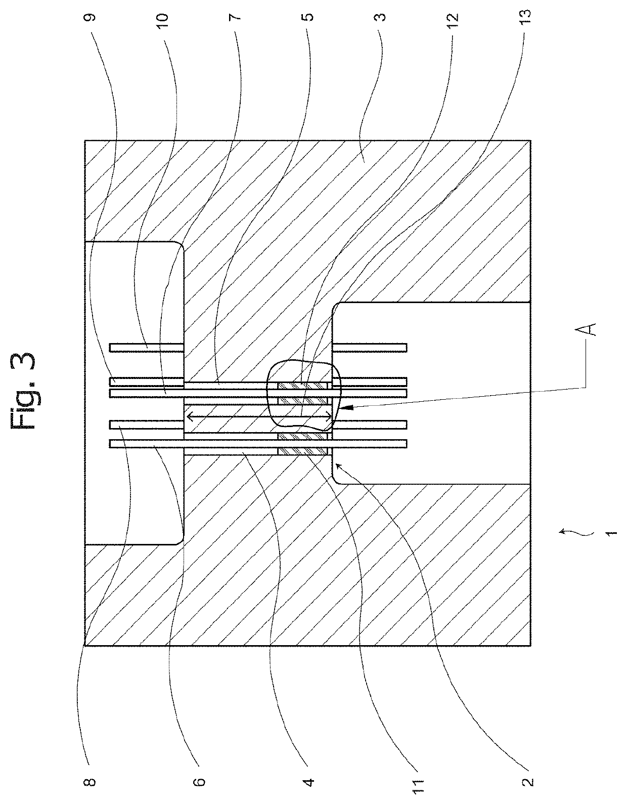
[0074]First referring to FIG. 3, a feed-through without pressure compensator will be described, in order to be able by way of this description to better understand the effects and advantages according to the invention further below.

[0075]Reference numeral 1 in FIG. 3 designates the feed-through 1 to be described as a whole, which experiences the pressures that are to be mastered by the feed-through 1 at the pressure-facing side 2 of the base body 3, in particular the side facing external pressure.

[0076]Through-holes 4 and 5 extend through the base body 3, with functional elements 6 and 7, respectively, arranged therein, which are retained therein by a compression glass seal, as will be described in more detail below.

[0077]Although further functional elements 8, ...


PUM

PropertyMeasurementUnit
pressuresaaaaaaaaaa
pressuresaaaaaaaaaa
pressuresaaaaaaaaaa

Abstract

A feed-through for high external pressure applications and methods of producing are provided. The feed-through includes a base body, a through-hole extending through the base body, and a functional element. The functional element is arranged inside the through-hole. The functional element is connected to the base body in fluid-tight manner with a pressure compensator and an insulating material that at least partially surrounds the functional element and establishes the fluid-tight connection. The pressure compensator increases pressure resistance of the fluid-tight connection of the functional element to the base body against pressure.

Description

CROSS REFERENCE TO RELATED APPLICATIONS[0001]This application is a continuation of International Application PCT / EP2017 / 054329 filed Feb. 24, 2017, which claims benefit under 35 USC § 119 of German Application 102016103485.1 filed Feb. 26, 2016, the entire contents of both of which are incorporated herein by reference.BACKGROUND1. Field of the Invention[0002]The invention relates to feed-throughs for high external pressure applications and to methods for producing such feed-throughs.2. Description of Related Art[0003]For a variety of applications, feed-throughs are used which have to reliably withstand high external pressure. In particular if these feed-throughs come into contact with fluids under high pressure on one side thereof, their reliable and safe use and resistance under long-term operation is of great importance, including in terms of safety. Such applications include deepwater facilities such as production and exploration facilities, i.e. in the exploration and / or product...

Claims


Application Information

Patent Timeline
Patent Type & Authority Patents(United States)
IPC IPC(8): H01B17/30H01M8/02
CPCH01B17/305H01B17/306Y02T90/32Y02P70/56H01M2250/20H01M8/02Y02E60/50Y02T90/40Y02P70/50H01B19/00H01M8/04201
Inventor SUTTNER, JÜRGENFINK, THOMAS
Owner SCHOTT AG
Learn More