Quick charger and quick charging system for electric vehicle

a quick charging and electric vehicle technology, applied in the direction of electric vehicle charging technology, charging stations, transportation and packaging, etc., can solve the problems of difficult bend of the charging cable of the quick charger, difficulty in operation, etc., and achieve the effect of reducing the burden on the user in operation and excellent safety

Inactive Publication Date: 2015-06-23
HITACHI LTD
View PDF14 Cites 25 Cited by
  • Summary
  • Abstract
  • Description
  • Claims
  • Application Information

AI Technical Summary

Benefits of technology

[0009]Especially, when assuming a self-service system in which a user charges a vehicle by himself / herself, it is important to consider the operability and safety.
[0013]In order to address the above-described problems of the related art, an object of the present invention is to provide a quick charging stand and a quick charging system for an electric vehicle in which a quick charging cable can be compactly stored, which is excellent in safety, and in which the burden on a user in operations is lightened.
[0015]According to an aspect of the present invention, even though the apparatus is a downsized and space-saving apparatus, it is possible to provide a quick charger for an electric vehicle in which the burden on a user in operations is lightened and which is excellent in safety.

Problems solved by technology

However, when the vehicle charger is installed at a narrow space such as a parking lot, downsizing and space-saving are required.
On the other hand, the charging cable of the quick charger becomes difficult to bend and becomes heavy due to its large diameter because an incorporated electric wire becomes thick to supply high-voltage power and a sufficient cladding thickness around the electric wire is required, thus resulting in a problem in operability.
When downsizing and space-saving are considered, it becomes difficult in operability to roll up and store a quick charging cable at a narrow space.
In contrast, when charging, it is necessary to rewind the charging cable, and thus the burden on a user in operability is increased.
Further, in a state where the charging cable is rolled up, the charging cable tends to be rolled due to the burden on the charging cable.
In addition, when the charging cable is pulled out, the charging cable does not become stable.

Method used


Image

  • Quick charger and quick charging system for electric vehicle
  • Quick charger and quick charging system for electric vehicle
  • Quick charger and quick charging system for electric vehicle

Examples


first embodiment

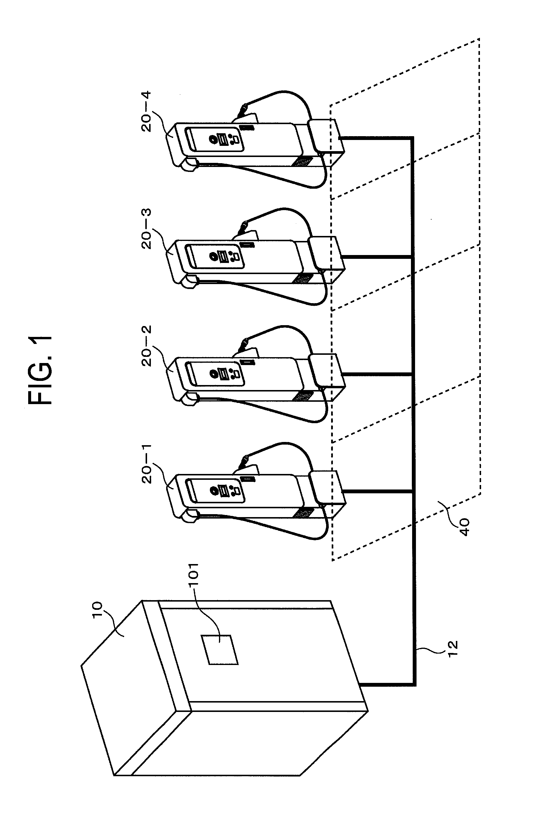
[0047]FIG. 1 is a diagram for showing a configuration of a quick charging system for an electric vehicle, with separated quick charging stands (quick chargers) according to a first embodiment of the present invention. In FIG. 1, the reference numeral 10 denotes a converter that is connected to 4 separated quick charging stands 20 (20-1, 20-2, 20-3, and 20-4) through a connection cable 12. The reference numeral 40 denotes parking spaces. The converter 10 includes an operation panel 101. It should be noted that one quick charging stand is installed at each parking space in the example of FIG. 1. However, the quick charging stands 20 may be installed so that one quick charging stand 20 can be shared by cars parked at two adjacent parking spaces 40. In addition, one converter and one to four quick charging stands may be combined in some cases in accordance with the conditions of the parking spaces.

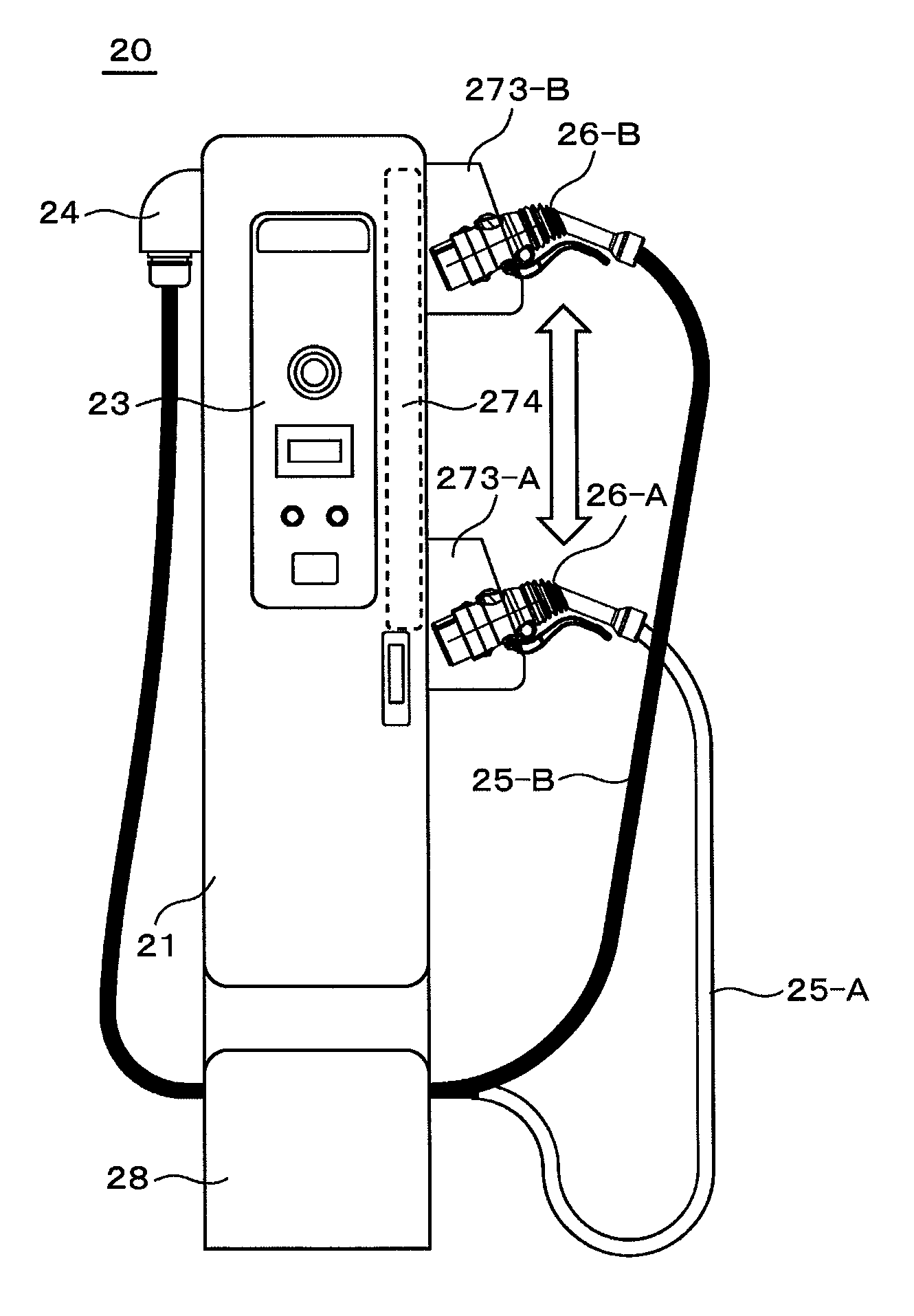
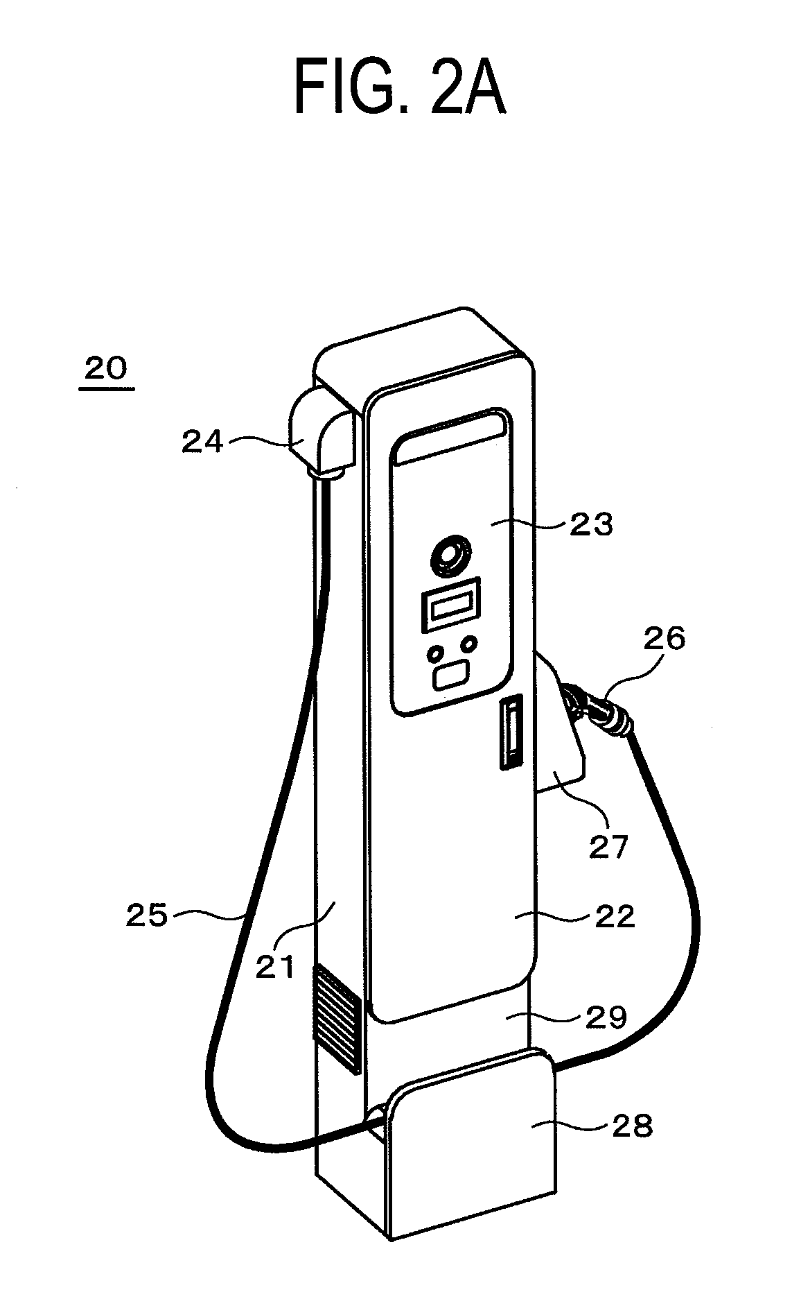
[0048]As shown in FIG. 2A and FIG. 2B, each of the separated quick charging stands 20 incl...

second embodiment

[0072]Next, a quick charging stand according to a second embodiment of the present invention will be described with reference to FIG. 11A and FIG. 11B. In this example, a member to reduce friction with the charging cable is provided at the cable receiving unit 280 of the charging cable receiver 28. Specifically, the second embodiment is different from the first embodiment in the structure of the cable receiving unit 280. It should be noted that the front part of the charging cable receiver 28 is not illustrated to easily understand. The configuration other than the cable receiving unit 280 is the same as that of the charging cable receiver 28 according to the first embodiment shown in FIG. 5.

[0073]In the example of FIG. 11A, rollers 291 are provided at the cable receiving unit 280 to rotatably hold the charging cable 25. In the case where the charging cable 25 is pulled in the right or left direction when a user operates the charging connector 26, the rollers 291 are rotated. Thus, ...

third embodiment

[0077]The example shown in FIG. 8A is a case in which the parking space in the indoor parking lot or the parking lot between buildings has little room on the front side, but has much room on the right and left sides. However, in the case of a parking space in a corner of an indoor parking lot, there is little room not only on the front side, but also on the right or left side or both sides. A third embodiment provides a quick charging stand that can be adapted to such a restricted parking space.

[0078]First, the example of FIG. 12A shows the quick charging stand 20 that can be adapted to a parking space with little room on the front and left sides. The third embodiment is the same as the first embodiment in that the charging cable outlet 24 is provided at an upper part of one side face of the body housing 21, the charging connector housing unit 27 is provided at an intermediate part on the right side, and the charging cable receiver 28 is provided at a lower part of the front face of...


PUM


Abstract

An object of the present invention is to provide a quick charger for an electric vehicle in which a quick charging cable can be compactly stored, which is excellent in safety, and in which the burden on a user in operations is lightened.Provided is a quick charger for an electric vehicle including: an operation panel provided on the front face of a body housing; an outlet for a charging cable provided on one side face of the body housing; a charging connector housing unit that is provided on the other side face of the body housing to hold a charging connector in the body housing; and a charging cable receiver that is provided at a lower part of the body housing, wherein the charging cable receiver has a function of holding an intermediate part of the charging cable.

Description

CLAIM OF PRIORITY[0001]The present application claims priority from Japanese Patent Application JP 2011-206095 filed on Sep. 21, 2011, The contents of which is hereby incorporated by reference into this application.FIELD OF THE INVENTION[0002]The present invention relates to a quick charger and a quick charging system for an electric vehicle, and particularly to a quick charging stand and a quick charging system suitable for a self-service system in which a user charges a vehicle by himself / herself.DESCRIPTION OF THE RELATED ART[0003]While entering a stage of full-scale, widespread use of electric vehicles, improvement of charging infrastructure is becoming important. The charging infrastructure includes a normal charging system by which a battery is charged for several hours and a quick charging system by which a battery is charged in a short time of 15 to 30 minutes. There is a growing need for the quick charging system to improve the convenience of electric vehicles.[0004]With re...

Claims


Application Information

Patent Timeline
Patent Type & Authority Patents(United States)
IPC IPC(8): H02J7/00B60L11/18
CPCB60L11/1825B60L11/185B60L2230/12Y02T10/7088Y02T10/7005Y02T90/121Y02T90/14Y02T90/128B60L53/11B60L53/18B60L53/302B60L53/305B60L53/31B60L53/67Y02T10/70Y02T10/7072Y02T90/12Y02T90/16
Inventor ODA, MASARUUMEZAWA, KOICHIUTSUKI, TOSHIYUKISAKAYORI, YOSHITOMOKAWAI, SHOJIHORII, MASAKATSU
Owner HITACHI LTD
Why Eureka
Try Eureka