Conveyor belt with improved edge configuration

a conveyor belt and edge configuration technology, applied in the direction of conveyors, transportation and packaging, etc., can solve the problems that the use of reinforcing bars alone has not been entirely successful in eliminating fatigue failures, and achieve the effect of reducing fatigue failures

Active Publication Date: 2015-06-23
CAMBRIDGE INT
View PDF10 Cites 28 Cited by
  • Summary
  • Abstract
  • Description
  • Claims
  • Application Information

AI Technical Summary

Benefits of technology

[0009]A flat wire conveyor belt comprising a plurality of spaced tractive rods; a plurality of rows of flat wire wickets transversely disposed with respect to a direction of travel and interconnecting said plurality of spaced tractive rods; a plurality of reinforcing bars; a plurality of belt drive clips; and a plurality of belt hold-down clips; wherein said conveyor belt includes opposing first and second outer edges and said plurality of reinforcing bars, belt drive clips and belt hold-down clips are disposed on at least one of the first and second outer edges of the flat wire conveyor belt, said reinforcing bars, belt drive clips and belt hold-down clips thereby strengthening said at least one outer edge for receiving tension during use and reducing fatigue failures on the driven edge of the conveyor belt.

Problems solved by technology

However, the use of reinforcing bars alone has not been entirely successful in eliminating fatigue failures on the positively driven edge 12 of the conveyor belt.

Method used


Image

  • Conveyor belt with improved edge configuration
  • Conveyor belt with improved edge configuration
  • Conveyor belt with improved edge configuration

Examples


second embodiment

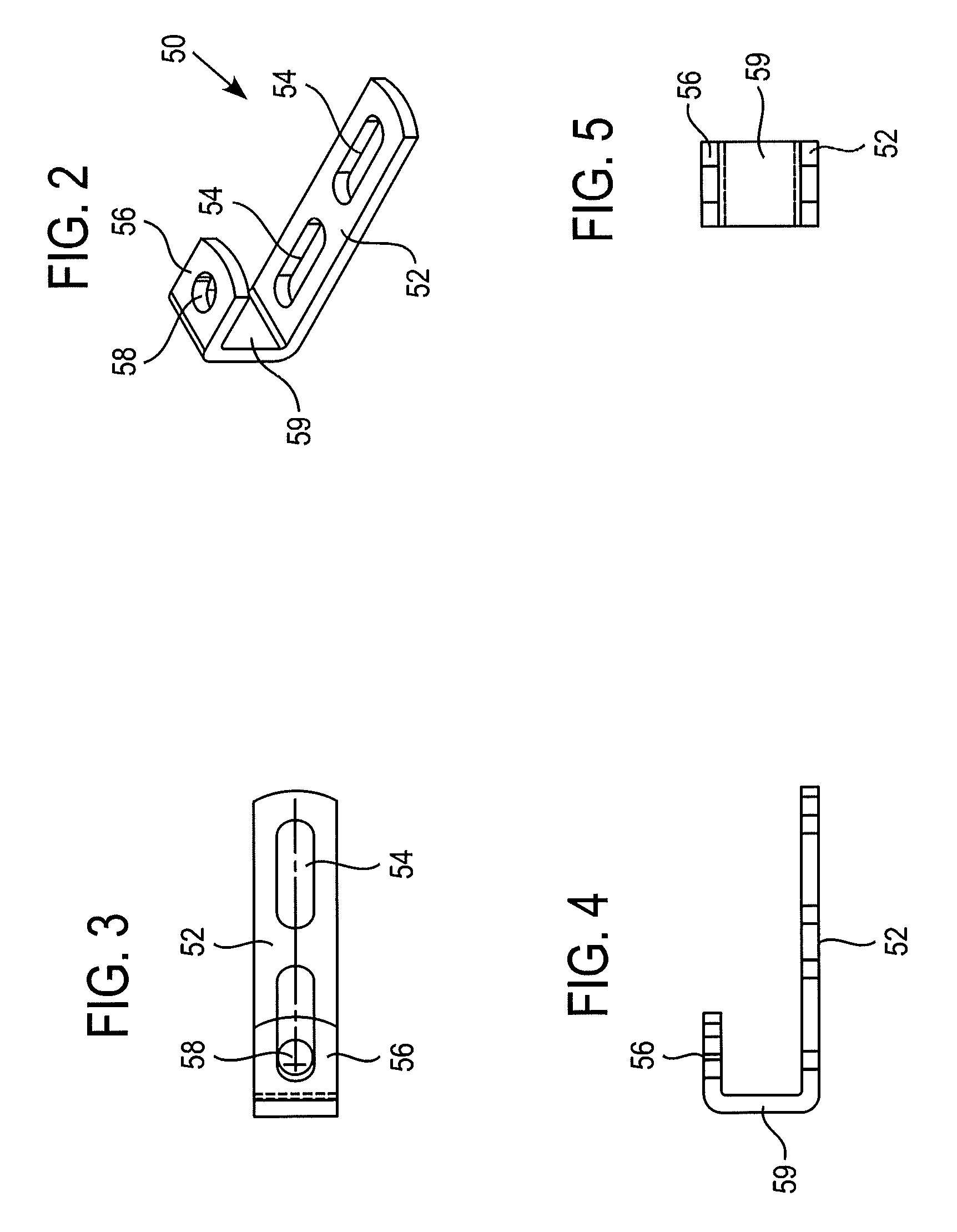
[0047]Referring to FIGS. 14-18, belt drive clip 500 according to the disclosure includes a first leg portion 520 having two elongated slot openings 540, a second leg portion 560 having an opening 580, and a side connecting portion 590 connecting the first and second leg portions 520, 560 together. Belt drive clip 500 further includes a bottom connecting portion 510.

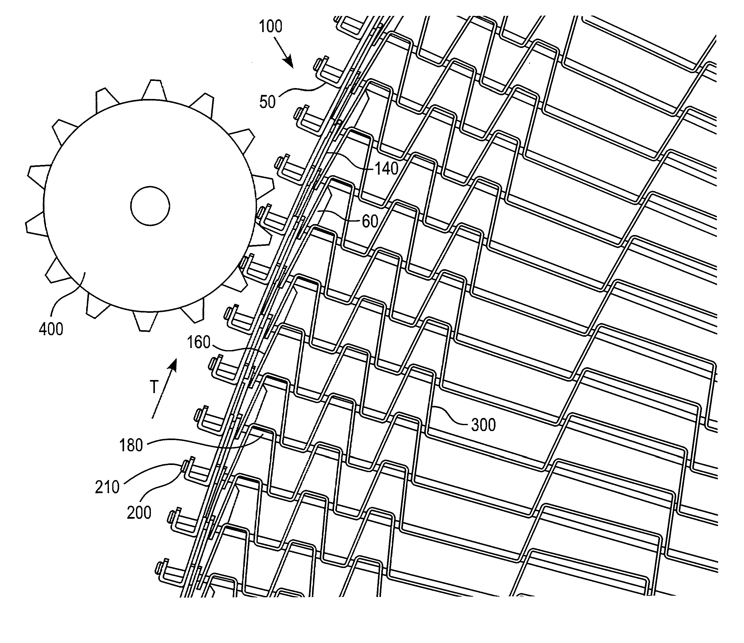
[0048]A conveyor belt in accordance with the second embodiment is shown generally in FIGS. 19-20 by reference numeral 200. Conveyor belt 200 preferably comprises a flat wire conveyor belt, although other belts configurations could of course be used. Conveyor belt 200 includes a plurality of spaced tractive rods 280 disposed in succession and transversely with respect to a direction of travel T as represented by arrow T of belt 200, each rod 280 having two ends (only one being shown) preferably terminating in a buttonhead 210.

[0049]Belt 200 includes a plurality of rows of wickets 260 transversely disposed with respect to t...

fourth embodiment

[0052]Referring to FIGS. 23-24, belt drive clip 700 includes a first leg portion 720 having an elongated slot opening 740, a second leg portion 760 having an opening 780, and an angular connecting portion 790 connecting the first and second leg portions 720, 760 together. Belt drive clip 700 further includes a side portion 710.

[0053]As shown, the belt drive clip 700 is retained and strengthened by the extension of the connecting rod 280 and welded outer buttonhead 210 through the second leg portion 760. An end portion 715 of the second leg portion 760 abuts against the connecting rod 280 to provide further stabilization of the same. Belt drive clip 700 is more simplistic than the second embodiment shown in FIGS. 14-18 and is also left and right belt edge reversible.

fifth embodiment

[0054]Referring to FIGS. 25-26, belt drive clip 800 includes a first leg portion 820 having an elongated slot opening 840, a second leg portion 860 having an opening 880, and an angular connecting portion 890 connecting the first and second leg portions 820, 860 together. Belt drive clip 800 further includes a rear leg portion 815 and a side portion 810 connecting the rear leg portion 815 to the second leg portion 860.

[0055]As shown, the belt drive clip 800 is retained and strengthened by the extension of the connecting rod 280 and welded outer buttonhead 210 through the second leg portion 860. As shown, rear leg portion 815 defines an inner leg of the clip 800 and second let portion 860 defines an outer leg of the clip against which the buttonhead 210 abuts. Rear leg portion 815 also includes a notch 825 against which the connecting rod 280 abuts to provide further stabilization of the same. During use, a force applied to drive clips 800 from a drive sprocket (not shown) is transf...


PUM


Abstract

A flat wire conveyor belt having a plurality of spaced tractive rods, a plurality of rows of flat wire wickets transversely disposed with respect to a direction of travel and interconnecting the plurality of spaced tractive rods, a plurality of reinforcing bars, a plurality of belt drive clips, and a plurality of belt hold-down clips. The plurality of reinforcing bars, belt drive clips and belt hold-down clips are disposed on at least one outer edge of the flat wire conveyor belt to reduce fatigue failures on the driven edges of the conveyor belt and thereby improve the edge drive capability thereof.

Description

TECHNICAL FIELD[0001]The present disclosure is directed to a conveyor belt, and more particularly to a flat wire conveyor belt having an improved edge configuration for maintaining belt orientation and providing improved positive edge drive capability.BACKGROUND OF THE DISCLOSURE[0002]The disclosure set forth herein relates to a spindle drive conveyor or chain conveyor, as shown for example in U.S. Pat. No. 5,228,557, the entire contents of which are hereby incorporated by reference. In a chain conveyor, as described therein, the belt is entrained and moved by means of drive units each comprising sprockets or toothed wheels engaging with one or both of the chains of the belt, to cause them to move forward at the desired speed. The toothed wheels generally engage the chain tangentially and / or from underneath, and are arranged in a vertical plane passing through the chain.[0003]With reference to FIG. 1, when a conveyor belt 10 is used in a spindle drive conveyor or similar system, ten...

Claims


Application Information

Patent Timeline
Patent Type & Authority Patents(United States)
IPC IPC(8): B65G17/22B65G15/30B65G17/08
CPCB65G15/30B65G17/083B65G17/22
Inventor SALSONE, FRANKPERDUE, THOMAS O.MESSICK, JR., GEORGE H.
Owner CAMBRIDGE INT
Why Eureka
Try Eureka