Fiber alignment using a channel incorporating a fulcrum structure

a fiber support and channel technology, applied in the direction of optical waveguide light guide, instruments, optics, etc., can solve the problems of time-consuming and expensive high-volume production applications, significant cost saving in optical packaging, and inability to provide passive alignment with micron-level tolerances, etc., to achieve accurate and precise form a v-groove and reduce fatigue failure

Inactive Publication Date: 2005-03-01
QORVO US INC
View PDF8 Cites 2 Cited by
  • Summary
  • Abstract
  • Description
  • Claims
  • Application Information

AI Technical Summary

Benefits of technology

[0009]In accordance with the present invention, a fulcrum is formed in approximately the center area of a channel used to support an optical fiber. A fiber is positioned in the channel and pressed in place against the fulcrum with a downward force. The presence of the fulcrum results in the fiber only contacting the channel along the extent of the fulcrum. The fulcrum functions as a pivot point, allowing for a “gross” movement of the fiber outside of the package to provide for a “fine” adjustment of the opposing (perhaps lensed) endface of the fiber inside the package, resulting in submicron alignment between the fiber and an associated optical device.
[0011]In a preferred alignment technique using the arrangement of the present invention, the fiber is first processed to form a gentle bend in a region between the package wall and the fiber channel (i.e., introducing a plastic deformation along a section of the fiber). The bend is formed to provide an initial downward bias along the fiber, with the endface of the fiber exhibiting a downward angle with respect to the optical axis. This initial downward bias will result in pressing the fiber against the fulcrum, insuring that the fiber will stay in place along the fulcrum during alignment. The induced bend should remain below the curvature that induces microbending losses, yet the curvature needs to be sufficient to allow for x-y-z movement of the fiber during alignment. Moreover, the bend functions to reduce fatigue failure during the lifetime of the packaged fiber, by allowing for the expansion and contraction (elastic deformation) of the fiber between the fixed point at the fulcrum and its fixed location at the package wall.

Problems solved by technology

Often referred to as “silicon optical bench” technology, the utilization of silicon may result in a significant cost saving in optical packaging over some of the more esoteric materials that have been used in the past.
Although such an arrangement is useful in a number of applications, the capability of providing passive alignment with micron-level tolerances becomes problematic, and the need to utilize a number of mating components (e.g., alignment detents and spheres, for example), becomes time-consuming and expensive for high volume production applications.

Method used


Image

  • Fiber alignment using a channel incorporating a fulcrum structure
  • Fiber alignment using a channel incorporating a fulcrum structure
  • Fiber alignment using a channel incorporating a fulcrum structure

Examples


Embodiment Construction

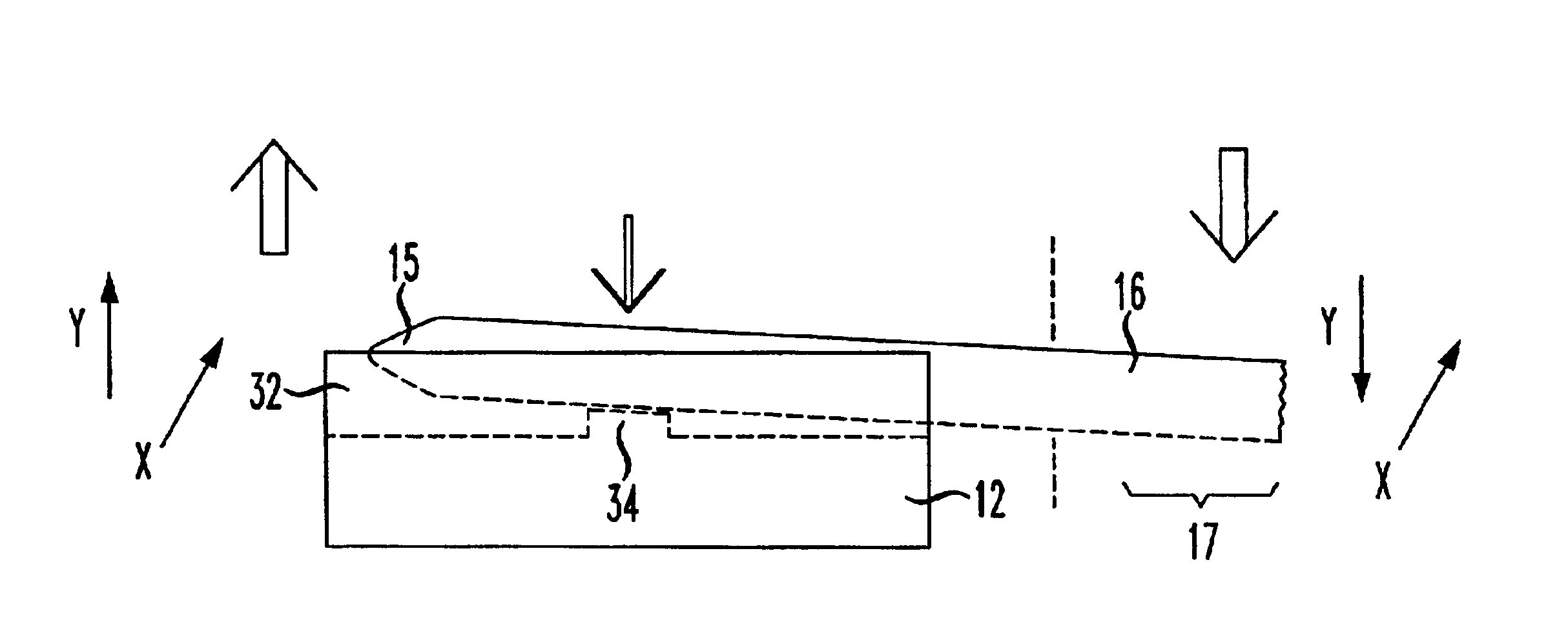
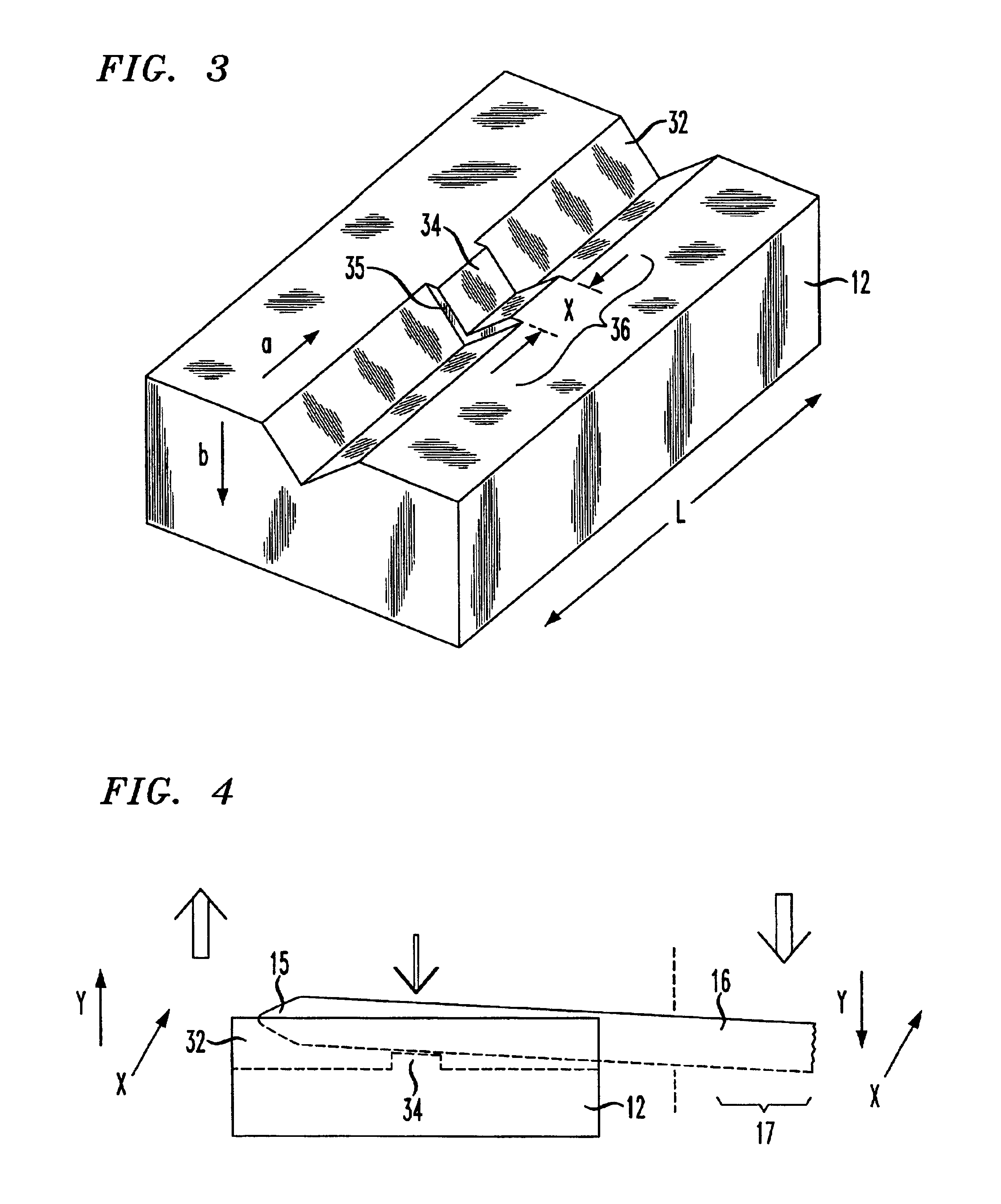
is a side view of an exemplary fulcrum V-groove substrate and coverplate subsequent to attaching the fiber to the alignment element;

[0020]FIG. 6 is a cut-away view of the arrangement of FIG. 5, taken along line 6—6;

[0021]FIG. 7 illustrates an exemplary embodiment of the present invention including a pair of fulcrum V-grooves formed on a single substrate; and

[0022]FIG. 8 illustrates an array embodiment of the present invention.

DETAILED DESCRIPTION

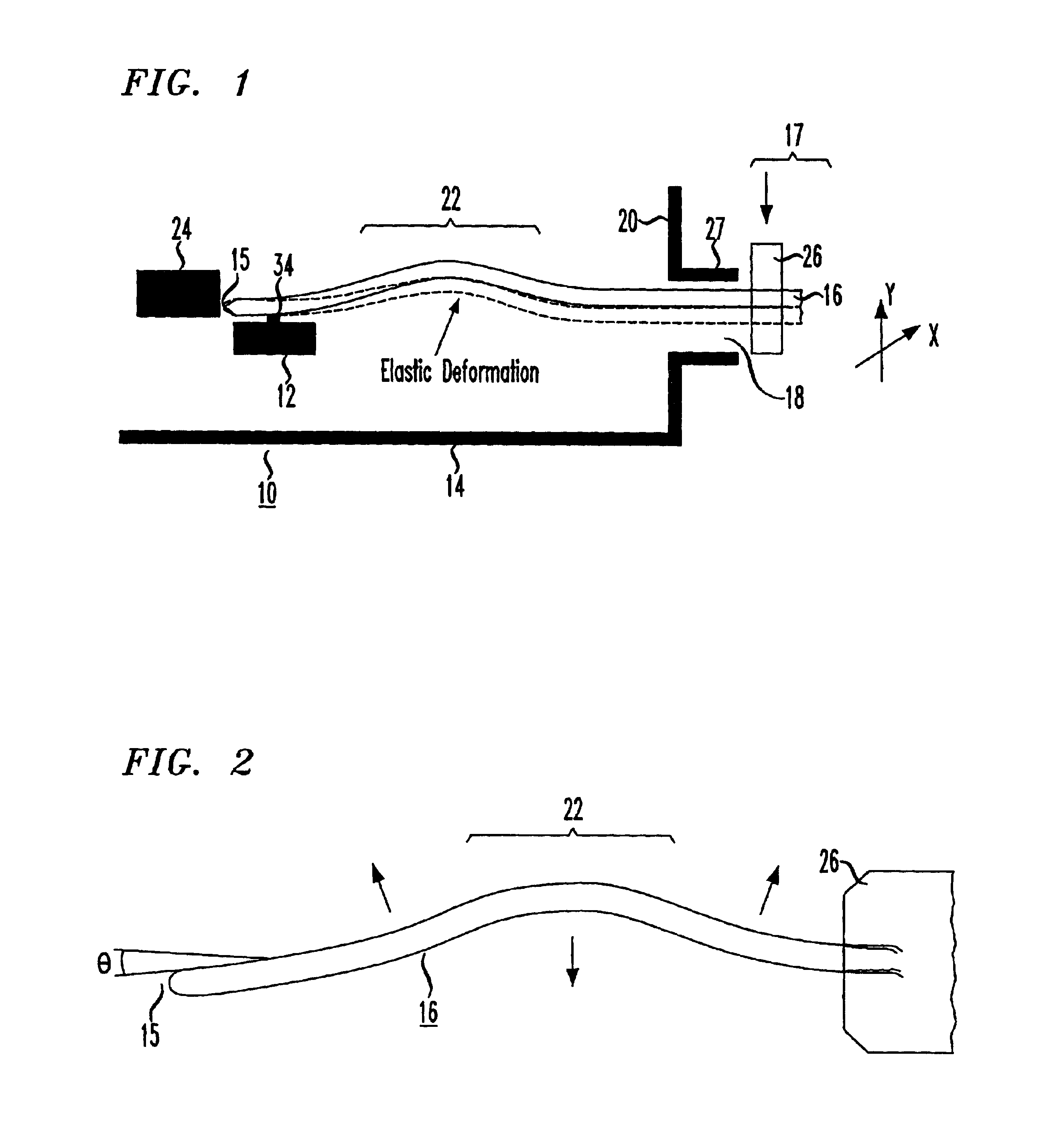
[0023]FIG. 1 illustrates an exemplary optical package 10 that includes and utilizes a fulcrum fiber alignment element 12 formed in accordance with the present invention. In general, optical package 10 comprises a housing 14 formed of a material such as Kovar, where an optical communication fiber 16 is inserted through an opening 18 in a sidewall 20 of package 10. In accordance with the present invention, and as will be discussed in detail below, communication fiber 16 may include a lensed endface 15 (see FIGS. 2 and 4), and advantageously is...


PUM


Abstract

Optical alignment between a communication optical fiber and an optical device is achieved by using a substrate including a fiber-holding channel formed in the top surface of the substrate. The channel is particularly formed to include a central fulcrum region, against which the fiber is pressed into as the fiber-to-device alignment is performed. In particular, the fulcrum functions as a pivot point to allow for the free endface of the fiber nearest the optical device to be adjusted (performing a “fine” adjustment) by manipulating the opposing end of the fiber (using a “gross” movement) until alignment with the optical device is achieved. A reduction of, for example, 14:1 between the gross movement and the fine adjustment can be achieved by using the inventive fulcrum structure.

Description

TECHNICAL FIELD[0002]The present invention relates to a fiber alignment arrangement and, more particularly, to the use of a fiber-supporting channel including a fulcrum disposed along its longitudinal axis, the fulcrum used as a pivot point to assist in providing alignment between a fiber and an associated optical device.BACKGROUND OF THE INVENTION[0003]In the realm of optical device packaging, there is beginning to develop a number of assemblies which utilize a single crystal semiconductor material (such as silicon) as the support structure for the various optical devices. Often referred to as “silicon optical bench” technology, the utilization of silicon may result in a significant cost saving in optical packaging over some of the more esoteric materials that have been used in the past. More importantly, silicon processing technology has advanced to the stage where a number of relatively simple procedures (e.g., oxidation, isotropic etching, anisotropic etching, etc.) may be utili...

Claims


Application Information

Patent Timeline
Patent Type & Authority Patents(United States)
IPC IPC(8): G02B6/42G02B6/36G02B6/38
CPCG02B6/4226G02B6/3636G02B6/3652G02B6/3692G02B6/3803G02B6/4249G02B6/4238G02B6/4239G02B6/4225
Inventor FREUND, JOSEPH MICHAELGEARY, JOHN MICHAEL
Owner QORVO US INC
Why Eureka
Try Eureka