Flat panel monitor ceiling mounting system

a technology for mounting systems and monitors, applied in the direction of filing cabinets, filing cabinets, stands/trestles, etc., can solve the problems of time-consuming and costly mounting of conventional mounting techniques which typically use rigid poles, and achieve the effect of additional support and stability

Inactive Publication Date: 2015-06-23
COMP SPORTS SYST
View PDF8 Cites 9 Cited by
  • Summary
  • Abstract
  • Description
  • Claims
  • Application Information

AI Technical Summary

Benefits of technology

[0042]Mounting system 150 is used when the suspending cables 110 or chains are of uneven length, or when it is desired to move the monitors 18 closer to the ceiling without altering the existing cables or chains. This embodiment uses two horizontal support members 114b and 114a instead of a single horizontal support member 114. The cables 110 are threaded between the second horizontal support member 114a, here the upper horizontal support member, and the monitor 18 or monitors 18. In some configurations the cables 110 are in contact with the second horizontal support member 114a. The placement of the second horizontal support member 114a determines the tile angle of the monitor 18 (or monitors in a multiple monitor arrangement). The cables 110 are then attached to the lower horizontal support member 114b using turnbuckles 156 with quick links 154 or other adjustable or fixed devices to securely couple the cables or chains to the lower horizontal support member 114b. Adjusting one or both of the turnbuckles 156, as shown in FIG. 11 can compensate for uneven lengths of the two cables or chains. Also, by putting the lower horizontal support member 114b through mounting holes in the vertical brackets 112′ which are lower to the bottom of the monitor, more of the cable or chain is placed behind the monitors, which has the effect of raising the monitors 18 closer to the ceiling. Optional brackets 160a and 160b can be attached to flanges 138 on the vertical brackets 112′ to provide additional support and stability when multiple display components 18 are suspended from the ceiling. The brackets 160 can act as shelves or stability bars, and also serve to adjust and set the horizontal spacing (from about zero to any desired distance) between multiple display components 18.

Problems solved by technology

Conventional mounting techniques which typically use a rigid pole can be time consuming to mount and costly because of the requirement to mount a plate to the ceiling.

Method used


Image

  • Flat panel monitor ceiling mounting system
  • Flat panel monitor ceiling mounting system
  • Flat panel monitor ceiling mounting system

Examples


Embodiment Construction

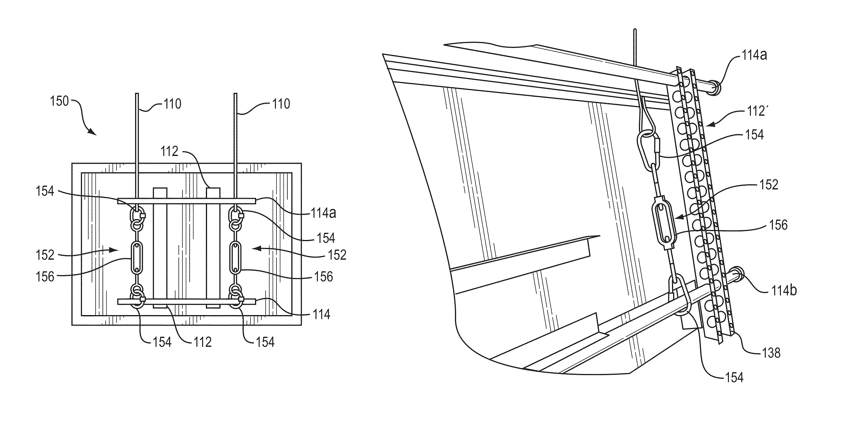
[0028]Embodiments according to this invention allow for leveraging readily available support structures with wire, cable, rope or chains or any other strong flexible material to provide a mounting system to suspend one or more display components from a ceiling.

[0029]As used herein the term “component,”“display component” or “display” refers to any monitor, display monitor, including but not limited to, flat screen displays, LCD displays, plasma displays and other display technologies embodied in a monitor. Embodiments of the invention can be used with any display suitable for ceiling mounting.

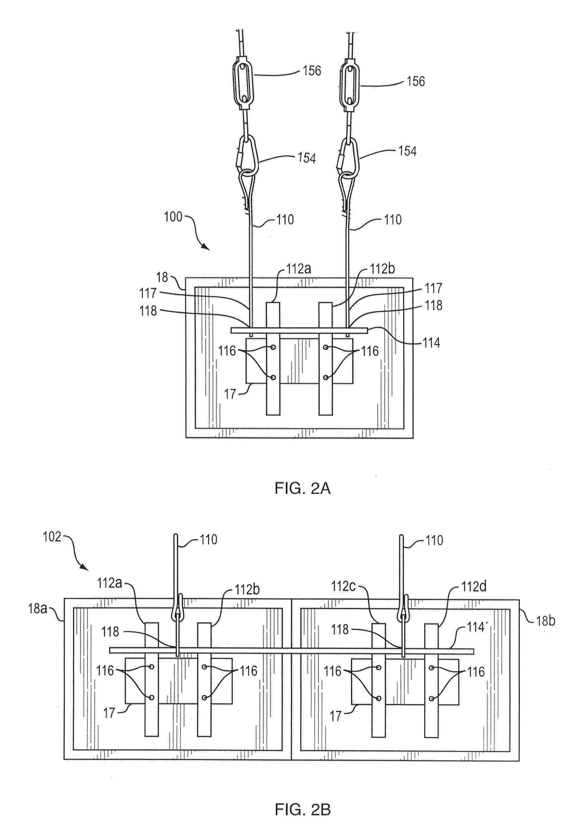
[0030]Now referring to FIG. 2A, a mounting system 100 for suspending a single component display includes a plurality of cables 110 each having a first end adapted to be flexibly attached to the ceiling structure (not shown) and second ends 117, a plurality of fasteners 118 coupled to corresponding ones of second ends 117 of the plurality of cables 110, and a horizontal support member 114 couple...


PUM


Abstract

A mounting system provides an inexpensive and flexible system to suspend a display component from a ceiling. The system further provides a system to suspend multiple display components. An alternate arrangement provides integrated leveling and height adjustment controls. A method of adjusting a viewing angle of the display component is also disclosed.

Description

CROSS REFERENCE TO RELATED APPLICATIONS[0001]This application claims the benefit of the filing date of earlier filed U.S. Provisional Patent Application having Ser. No. 61 / 265,081 entitled “FLAT PANEL MONITOR CEILING MOUNTING SYSTEM AND METHOD,” filed Nov. 30, 2009, that shares inventorship with the present application. This application claims the benefit of the filing date of earlier filed U.S. Provisional Patent Application having Ser. No. 61 / 359,136 entitled “FLAT PANEL MONITOR CEILING MOUNTING SYSTEM AND METHOD”, filed Jun. 28, 2010, that shares inventorship with the present application. The entire teachings and contents of these patent applications are hereby incorporated by reference herein in their entireties.BACKGROUND[0002]It is often necessary to suspend one or more flat screen displays from a ceiling for purposes of showing TV programs, movies, sports, schedules, scoring, or any other type of entertainment or information which can be displayed on such devices. These displ...

Claims


Application Information

Patent Timeline
Patent Type & Authority Patents(United States)
IPC IPC(8): B42F13/00F16M13/02
CPCF16M13/027F16M13/02F16M11/10F16G11/12
Inventor HOUSMAN, CHARLES L.
Owner COMP SPORTS SYST
Why Eureka
Try Eureka