Pose estimation using long range features

a technology of long-range features and estimation methods, applied in the field of long-range estimation using long-range features, can solve problems such as difficulty in achieving very high accuracy

Active Publication Date: 2015-06-23
WAYMO LLC
View PDF12 Cites 64 Cited by
  • Summary
  • Abstract
  • Description
  • Claims
  • Application Information

AI Technical Summary

Benefits of technology

[0007]A further aspect of the disclosure provides a non-transitory, tangible computer-readable storage medium on which computer readable instructions of a program are stored. The instructions, when executed by a processor, cause the processor to perform a method. The method includes receiving data collected by a first sensor while a vehicle is driving on a roadway, the first sensor having a first sensor range; using the received data from the first sensor to generate a map of the vehicle's environment within the first sensor range; estimating the vehicle's geographic location and heading by comparing the generated map to a stored map identifying the geographic locations of objects including reference objects having particular retroreflective, brightness, or intensity characteristics; receiving data collected by a second sensor while the vehicle is driving on the roadway, the second sensor having a second sensor range greater than the first sensor range; identifying a reference object having a particular retroreflective, brightness, or intensity characteristic from the data collected by the second sensor outside of the first sensor range; correlating the identified reference object to a reference object of the stored map based on the particular retroreflective, brightness, or intensity characteristic; and using the correlation to refine the estimated heading of the vehicle.

Problems solved by technology

These approaches may result in noise or uncertainty in both the inertial pose estimation and localization stages that makes it difficult to achieve very high accuracy results.

Method used


Image

  • Pose estimation using long range features
  • Pose estimation using long range features
  • Pose estimation using long range features

Examples


Embodiment Construction

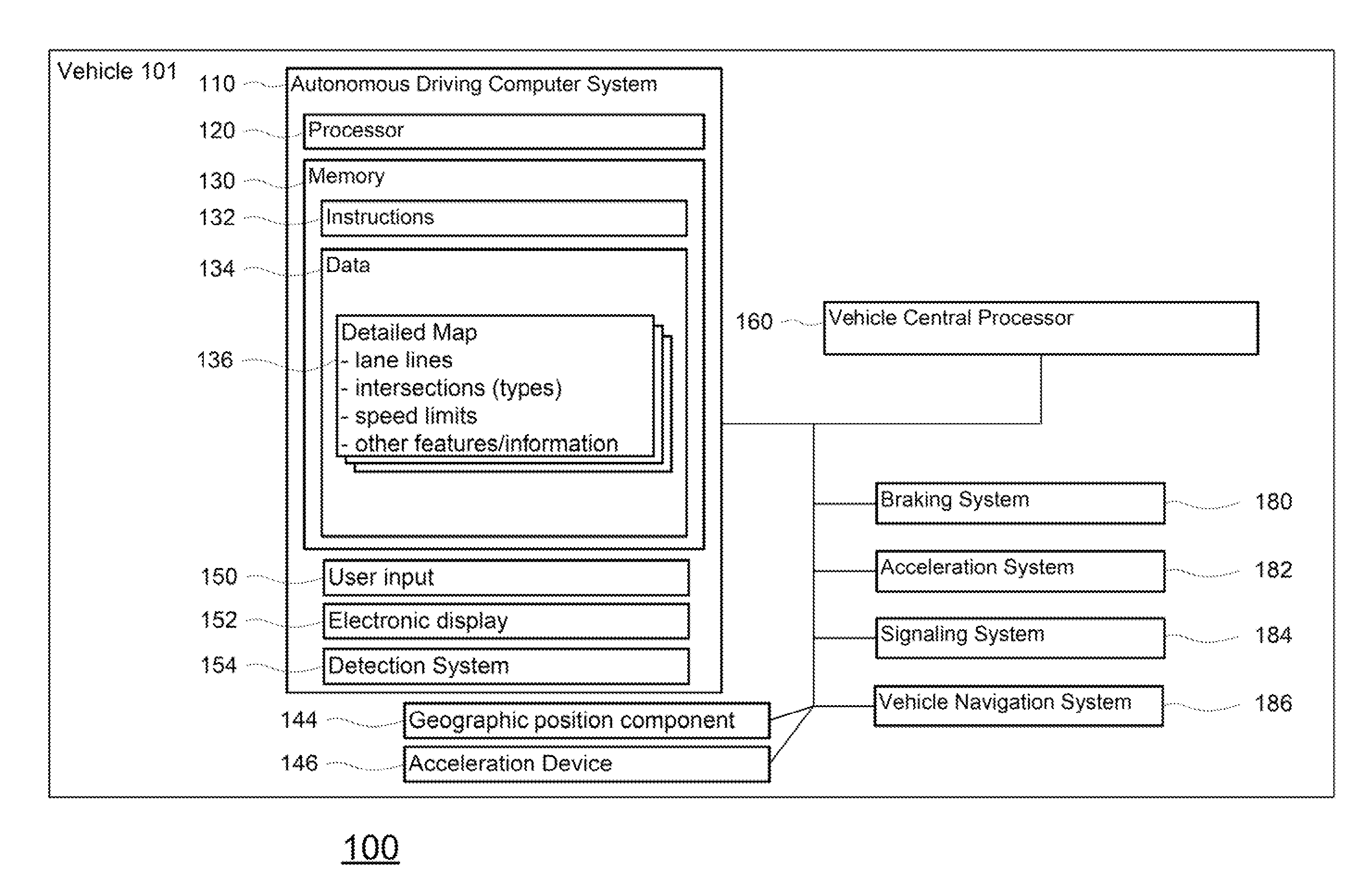
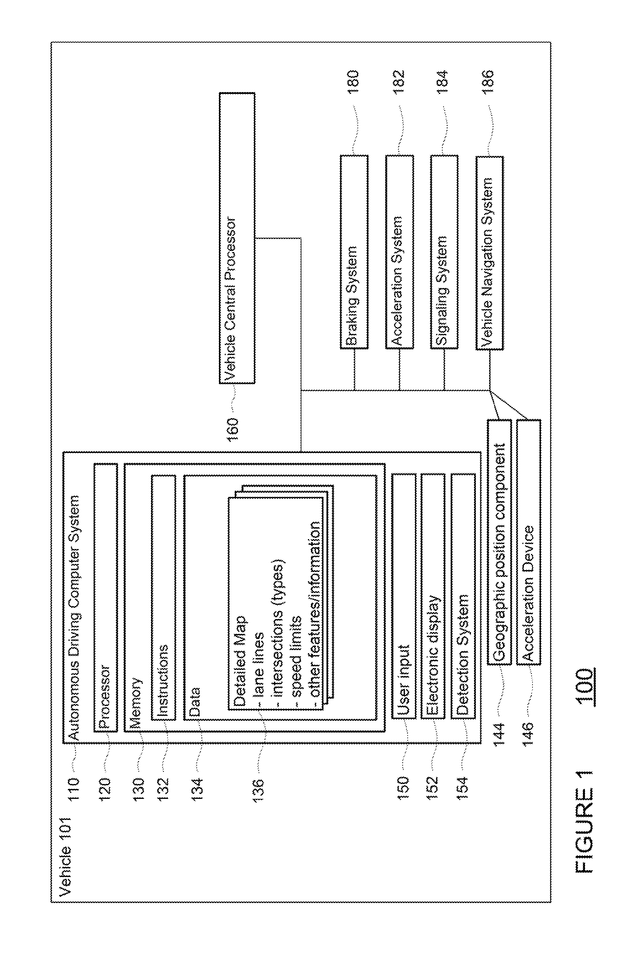
[0021]The disclosure relates generally to using an object detected at long range to increase the accuracy of a location and heading estimate based on near range information. For example, an autonomous vehicle may use data points collected from a sensor such as a laser to generate an environmental map of environmental features around the vehicle. The environmental map may be then compared to pre-stored map data to determine the vehicle's geographic location and heading (for example, latitude, longitude, and altitude coordinates and heading).

[0022]A second sensor, such as a laser or camera, having a longer range than the first sensor may detect an object outside of the range and field of view of the first sensor used to generate the environmental map. For example, the object may have retroreflective, brightness, or intesity properties which make it identifiable in a camera image or from laser data points at longer ranges, for example, 50, 75, 100, 150, 200 meters or more. The location...


PUM


Abstract

Aspects of the present disclosure relate to using an object detected at long range to increase the accuracy of a location and heading estimate based on near range information. For example, an autonomous vehicle may use data points collected from a sensor such as a laser to generate an environmental map of environmental features. The environmental map is then compared to pre-stored map data to determine the vehicle's geographic location and heading. A second sensor, such as a laser or camera, having a longer range than the first sensor may detect an object outside of the range and field of view of the first sensor. For example, the object may have retroreflective properties which make it identifiable in a camera image or from laser data points. The location of the object is then compared to the pre-stored map data and used to refine the vehicle's estimated location and heading.

Description

BACKGROUND[0001]Autonomous vehicles use various computing systems to aid in the transport of passengers from one location to another. Some autonomous vehicles may require some initial input or continuous input from an operator, such as a pilot, driver, or passenger. Other systems, for example autopilot systems, may be used only when the system has been engaged, which permits the operator to switch from a manual driving mode (where the operator exercises a high degree of control over the movement of the vehicle) to an autonomous driving mode (where the vehicle essentially drives itself) to modes that lie somewhere in between.[0002]When operating in an autonomous mode, these vehicles need to be able to accurately estimate their relative geographic location in the world. To do this, autonomous vehicles typically combine inertial pose estimation systems (e.g., using gyros, accelerometers, wheel encoders, GPS) and map-based localization approaches (e.g. generating a local map using onboa...

Claims


Application Information

Patent Timeline
Patent Type & Authority Patents(United States)
IPC IPC(8): G06F19/00G01C21/28G01C21/26G01S13/88
CPCG01C21/26G01C21/20G01S17/875G01S17/89G01C21/30
Inventor FERGUSON, DAVID I.SILVER, DAVID
Owner WAYMO LLC
Why Eureka
Try Eureka