Automatic screw tightening apparatus

a screw tightening and screw technology, applied in the direction of screwdrivers, metal-working apparatus, wrenches, etc., can solve the problems of screw tightening apparatus disadvantageous in space, screw tightening apparatus is large, screw tip of screws often getting stuck in the hose, etc., and achieve the effect of reducing the movement range of the screw tightening mechanism

Active Publication Date: 2015-06-30
OHTAKE ROOT IND
View PDF4 Cites 6 Cited by
  • Summary
  • Abstract
  • Description
  • Claims
  • Application Information

AI Technical Summary

Benefits of technology

[0007]The present invention has been made considering the above-mentioned problems and is to provide an automatic screw tightening apparatus for automatically tightening a screw against a predetermined screwed portion of a subject by a screw tightening mechanism in which smooth and automatic assembling is possible, a fore end portion of the screw tightening mechanism smoothly moves up and down without being connected to a hose or others, the screw tightening mechanism is small-sized and compact, and the movement range of the screw tightening mechanism is reduced.
[0010]According to the automatic screw tightening apparatus of the embodiment of the present invention, since screws are transferred with the head portions S1 of the screws being in the lead by the screw transferring mechanism using compressed air from the screw feeding mechanism, the inner wall of the transfer tube is less damaged, the screws do not get stuck in the transfer tube, and it is possible to stabilize the posture of the screws so as to firmly engage the screws with the driver bit such that it is possible to stably feed the screws and improve reliability.
[0011]Further, it is possible to automatically and quickly tighten the screw engaged with the driver bit against the screwed portion of the subject. Furthermore, a configuration for engagement of the screw with the driver bit is simple, maintenance is easy, and the fabrication cost is low.

Problems solved by technology

For example, tips of screws often get stuck in the hose.
Further, since the screw feeding mechanism should move with the feeder hose attached to the screw tightening head, the screw feeding mechanism is large.
Furthermore, since the movement range of the screw tightening mechanism should be wide, the screw tightening apparatus is disadvantageous in space.
Moreover, unexpected accidents may happen due to contact of workers or subjects with the hose or others.

Method used


Image

  • Automatic screw tightening apparatus
  • Automatic screw tightening apparatus
  • Automatic screw tightening apparatus

Examples


Embodiment Construction

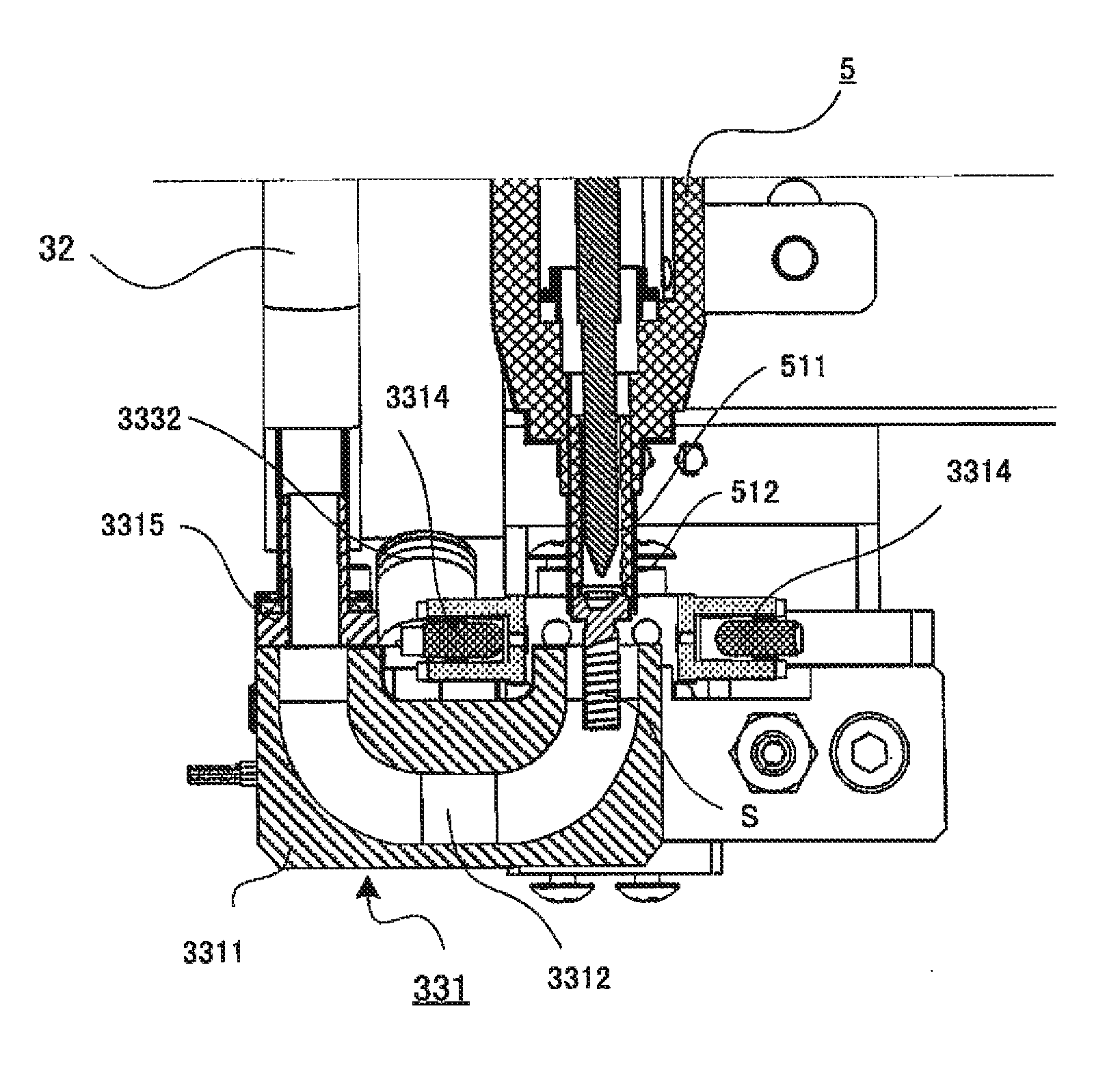
[0034]An embodiment of the present invention transfers screws one by one from a screw feeding mechanism to a screw tightening mechanism (driver) through a transfer tube such as a vinyl tube or hose with the head portions of the screws being in the lead in the transfer tube, and engages the head portion of each of the transferred screws with a fore end of a driver bit portion of the screw tightening mechanism by air suction of the screw tightening mechanism, thereby automatically and consecutively tightening the screws against desired screwed portions.

[0035]Hereinafter, an automatic screw tightening apparatus according to an embodiment of the present invention will be described in detail with reference to the accompanying drawings.

Whole Configuration

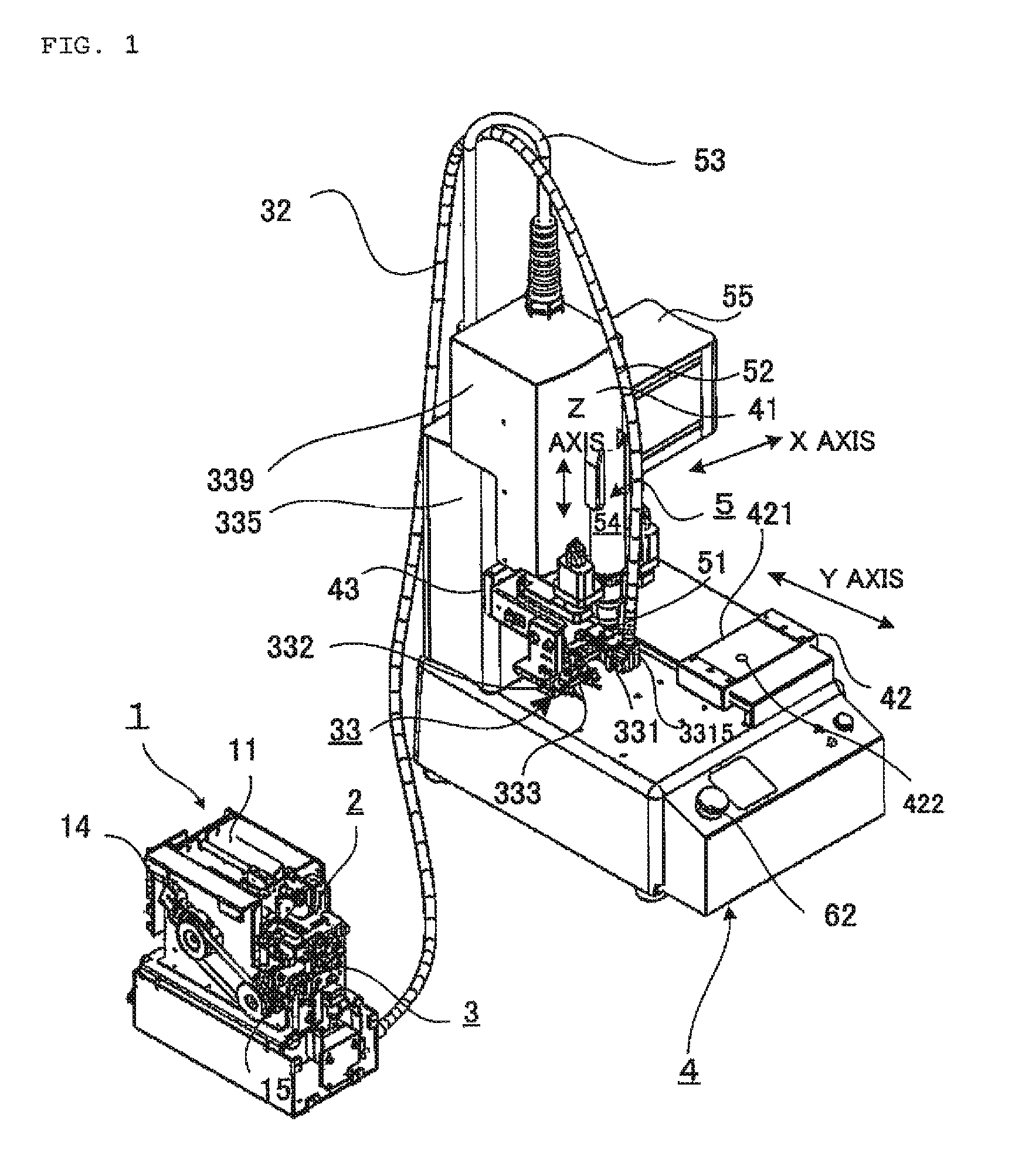
[0036]An automatic screw tightening apparatus with a screw feeding mechanism according to an embodiment of the present invention will be wholly and schematically described with reference to FIG. 1. FIG. 1 is a perspective view illustratin...


PUM


Abstract

In an automatic screw tightening apparatus, a feed head unit is movable to and from close contact with a driver bit portion. The driver bit portion contacts the screw and sucks the head portion of the screw in close contact. The feed head unit includes a longitudinal groove opened to the outside and connected to a vertically extending screw feed hole. Only a thread portion of the screw is capable of horizontally advancing and retreating in the longitudinal groove.

Description

BACKGROUND OF THE INVENTION[0001]1. Technical Field[0002]The present invention relates to an automatic screw tightening apparatus which automatically tightens a screw against a predetermined screwed portion of a subject by a screw tightening mechanism.[0003]2. Related Art[0004]In an automatic screw tightening apparatus according to the related art for automatically tightening a screw against a predetermined screwed portion of a subject by a screw tightening mechanism as disclosed in Japanese Patent Application Laid-Open No. Hei8-229752, predetermined screws are automatically fed from a screw feeding mechanism to a screw tightening head of a fore end of the screw tightening mechanism one by one. Then, the subject is fixed to a movable table and the screwed position of the subject moves to a predetermined position while the screw tightening head of the screw tightening mechanism moves. Next, a screw is tightened to assemble the subject.[0005]In this case, screws are fed to the screw t...

Claims


Application Information

Patent Timeline
Patent Type & Authority Patents(United States)
IPC IPC(8): B25B23/04B23P19/00B25B23/08B23P19/06B25B23/06
CPCB23P19/06B25B23/08B25B23/04B23P19/006B23P19/08B23Q7/06
Inventor OTA, YOSHITAKETAKAHASHI, HIROSHI
Owner OHTAKE ROOT IND
Why Eureka
Try Eureka