
Magnetic head parking system of hard disk drive

a magnetic head and parking system technology, applied in the field of hard disk drives, can solve the problems of frequent easy easy generation so as to reduce the possibility of damage to the magnetic head and reduce the movement range of the magnetic head

Inactive Publication Date: 2006-04-18
SAMSUNG ELECTRONICS CO LTD
View PDF3 Cites 4 Cited by
  • Summary
  • Abstract
  • Description
  • Claims
  • Application Information

AI Technical Summary

Benefits of technology

[0018]To solve the above and / or other problems, it is an aspect of the present invention to provide a magnetic head parking system of a hard disk drive which lowers a possibility of damage to a magnetic head due to a head slap by reducing a movement range of the magnetic head in upward and downward directions when an external impact is applied in a state in which an operation of the hard disk drive stops.
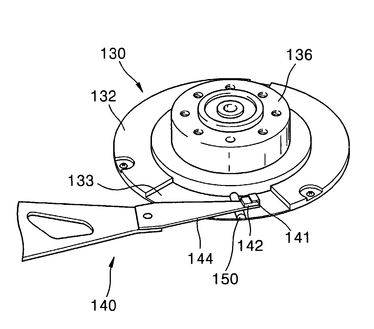
[0019]According to an aspect, a magnetic head parking system of a hard disk drive to move a magnetic head mounted on a slider of an actuator to move from a data zone of a magnetic disk and to be placed in a parking zone of the magnetic disk when the magnetic disk stops rotating, the magnetic head parking system comprising a head limiter provided on an upper surface of a flange of a spindle motor to protrude toward the magnetic disk and restricting a range of movement in upward and downward directions of the magnetic head placed in the parking zone of the magnetic disk.

Problems solved by technology

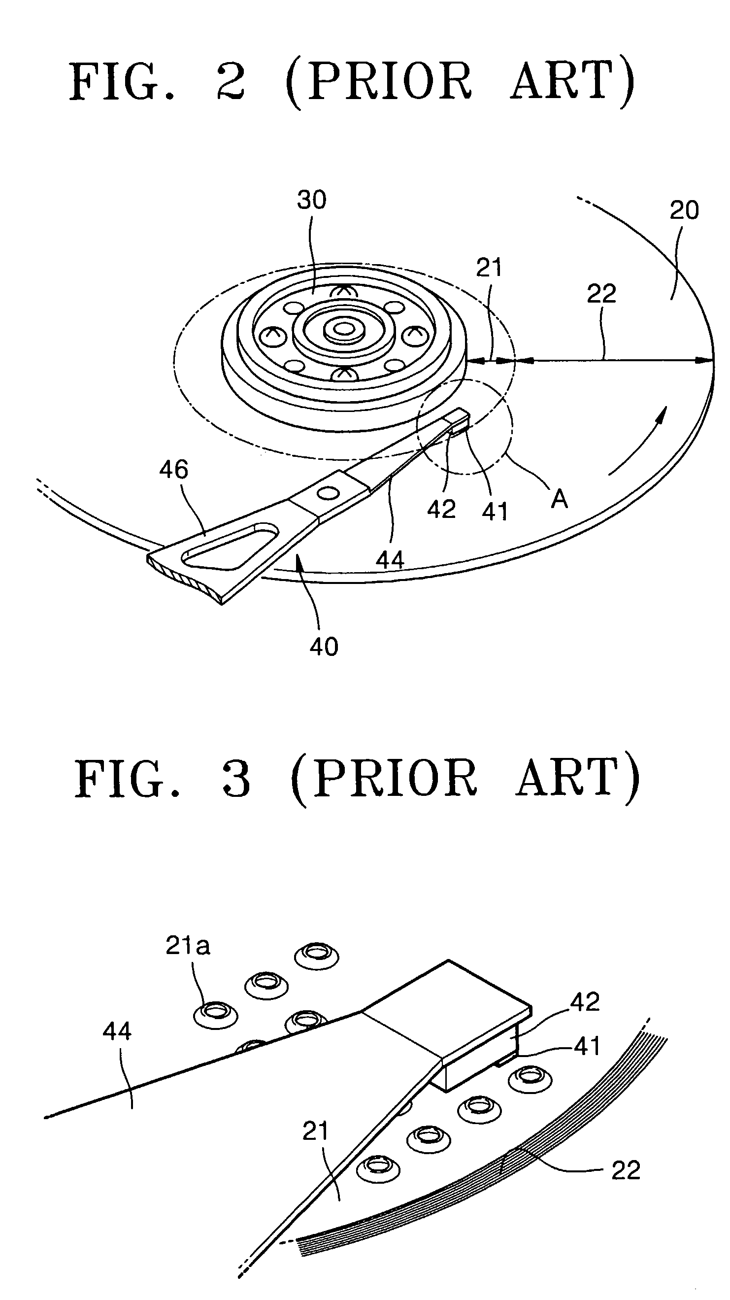
Damage to the magnetic head 41 is frequently generated in the magnetic head parking system having the above structure.
As a result, when a head slap is generated, the magnetic head 41 is easily damageable and the data recording / reproducing performance of the magnetic head 41 is lowered.

Method used


Image

  • Magnetic head parking system of hard disk drive
  • Magnetic head parking system of hard disk drive
  • Magnetic head parking system of hard disk drive

Examples


Embodiment Construction

[0032]Reference will now made in detail to the present embodiment of the present invention, examples of which are illustrated in the accompanying drawings, wherein like reference numerals refer to the like elements throughout. The embodiment is described below in order to explain the present invention by referring to the figures.

[0033]Referring to FIG. 5, a hard disk drive includes a magnetic disk 120 to store data, a spindle motor 130, and an actuator 140. A magnetic head parking system according to an embodiment of the present invention is provided in the hard disk drive.

[0034]The magnetic disk 120, where data is stored, is rotatable by the spindle motor 130. The magnetic disk 120 is installed at an outer circumference of a hub 136 of the spindle motor 130 and is fixed to rotate together with the hub 136 without escaping from the hub 136 by a disk clamp 160 coupled to an upper end portion of the hub 136 by plural screws 162. Three or more magnetic disks may be installed in a hard ...


PUM

PropertyMeasurementUnit
widthaaaaaaaaaa
range of movementaaaaaaaaaa
thicknessaaaaaaaaaa

Abstract

A magnetic head parking system of a hard disk drive to move a magnetic head mounted on a slider of an actuator from a data zone of a disk and to place the magnetic head in a parking zone thereof when the disk stops rotating. The magnetic head parking system includes a head limiter provided on an upper surface of a flange of a spindle motor to protrude toward the disk and restricting a range of movement in upward and downward directions of the magnetic head placed in the parking zone of the disk. The head limiter is provided at a position opposite to a position where the slider of the actuator is installed or at a position deviating from and / or adjacent to a position directly under the slider. Thus, when an external impact is applied and an operation of the hard disk drive is stopped, the range of the up and down movement of the magnetic head is limited by the head limiter, so that the possibility of the damage to the magnetic head due to the head slap can be lowered.

Description

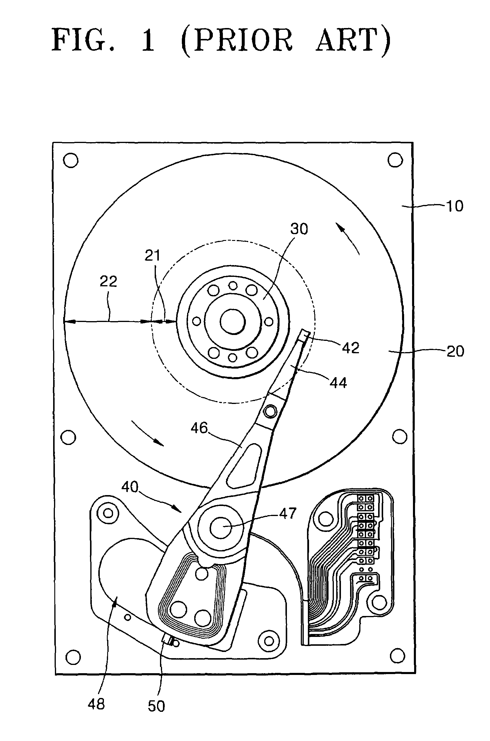
CROSS-REFERENCE TO RELATED APPLICATION[0001]This application claims the priority of Korean Patent Application No. 2002-41990 filed Jul. 18, 2002 in the Korean Intellectual Property Office, the disclosure of which is incorporated herein by reference.BACKGROUND OF THE INVENTION[0002]1. Field of the Invention[0003]The present invention relates to a hard disk drive, and more particularly, to a magnetic head parking system of a hard disk drive which enables stable parking of a magnetic head when an operation of the hard disk drive is stopped.[0004]2. Description of the Related Art[0005]A hard disk drive (HDD) is an auxiliary memory device of a computer which reproduces data stored on a magnetic disk or records data on the magnetic disk by using a magnetic head.[0006]FIG. 1 is a plan view illustrating a conventional hard disk drive. FIG. 2 is a partial perspective view illustrating part of a conventional magnetic head parking system. FIG. 3 is a perspective view illustrating a portion A s...

Claims


Application Information

Patent Timeline
Patent Type & Authority Patents(United States)
IPC IPC(8): G11B17/02G11B5/54G11B21/12
CPCG11B5/54G11B21/12
Inventor KIM, DO-WANJEONG, WOO-CHEOL
Owner SAMSUNG ELECTRONICS CO LTD
Learn More