Expansion joint system

a joint system and expansion joint technology, applied in the direction of roads, building components, roads, etc., can solve the problems of horizontal systems being subjected to pedestrian and/or vehicular traffic, leaking and/or deteriorating joints, and piers, columns and beams on bridges

Inactive Publication Date: 2015-06-30
EMSEAL JOINT SYST
View PDF366 Cites 86 Cited by
  • Summary
  • Abstract
  • Description
  • Claims
  • Application Information

AI Technical Summary

Problems solved by technology

Additionally, some horizontal systems may be subjected to pedestrian and / or vehicular traffic.
With particular regard to bridge expansion joints, a major cause of structural deterioration of piers, columns and beams on bridges is leaking and / or deterioration of joints.
Potential corrosion and subsequent spalling may occur thereby necessitating expensive reconstruction of beams, piers, columns, wing walls, and so forth.
Moreover, expansion joint products do not fully consider the irregular nature of some expansion joints.
In many products, this is a point of weakness, as the homogeneous nature of the product is interrupted.
In many situations, it is difficult or impossible to prefabricate these expansion joint transitions, as the exact details of the expansion joint and any transitions and / or dimensions may not be known at the time of manufacturing.
Additionally, in many products, the afore-referenced transitions present weak spots from both a water proofing aspect and a fire resistant aspect.
In many cases, however, there simply is not sufficient room in the physical space occupied by the expansion joint to accommodate both a fire rated system and a waterproofing system.

Method used


Image

  • Expansion joint system
  • Expansion joint system
  • Expansion joint system

Examples


Embodiment Construction

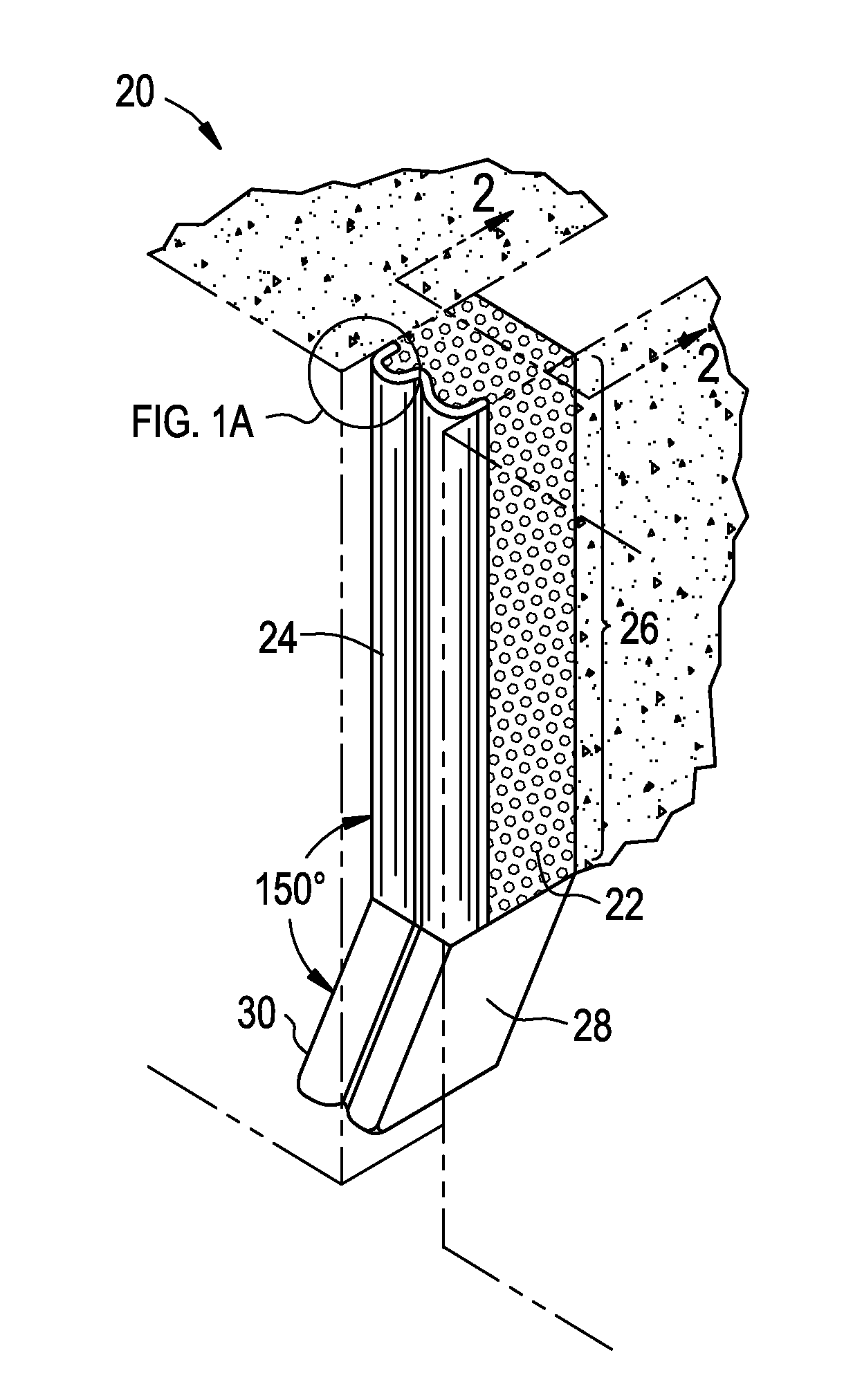
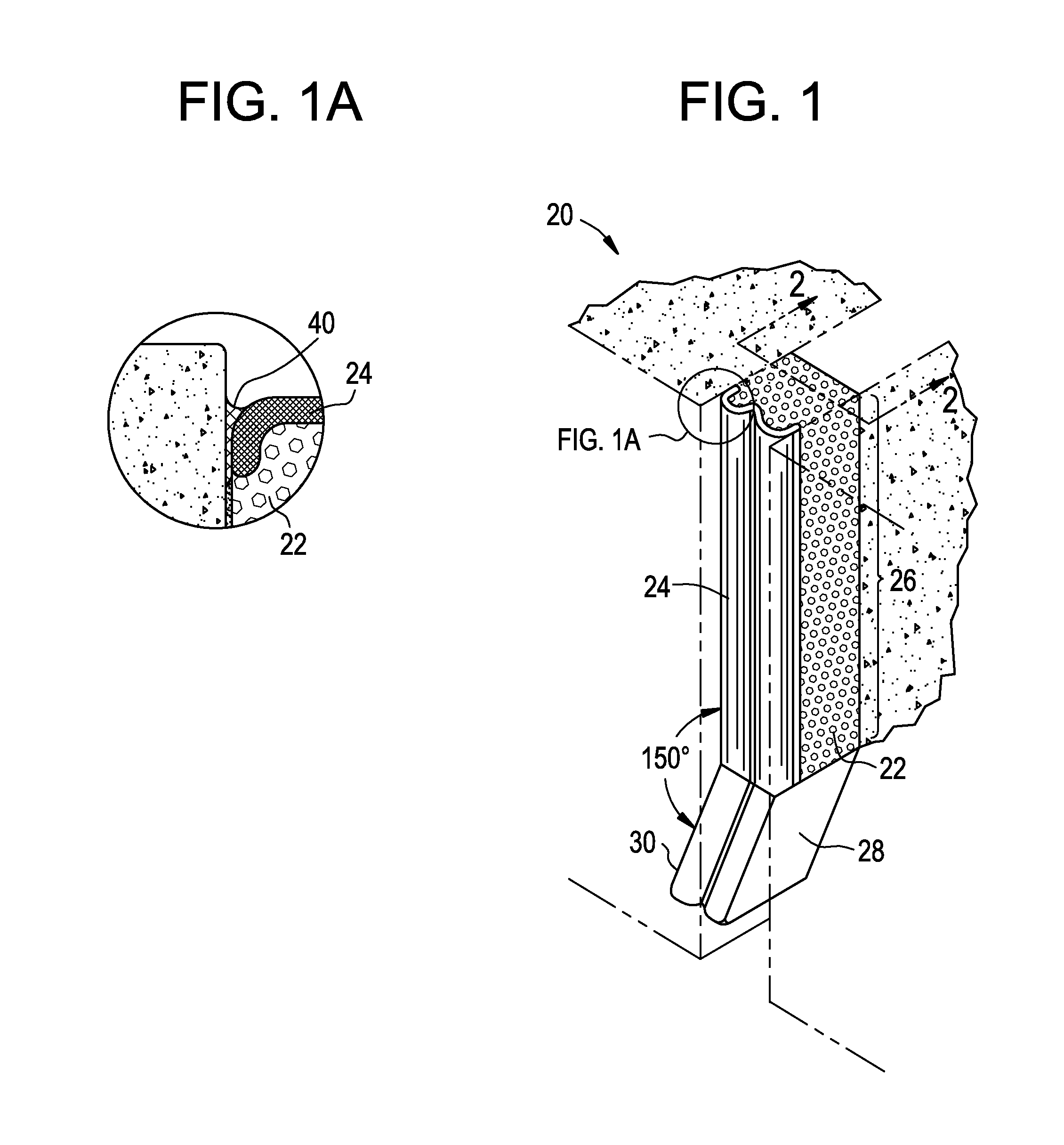
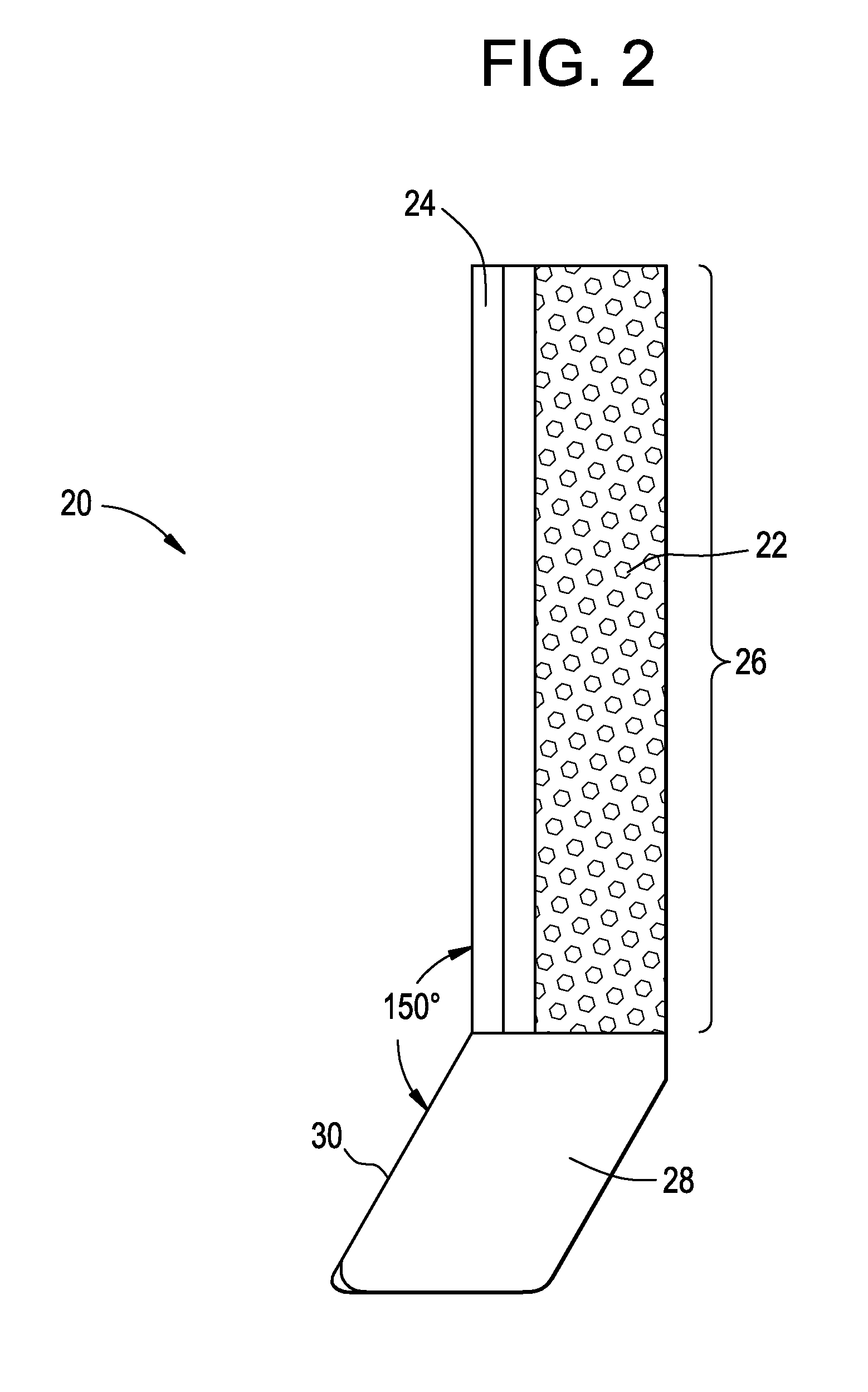
[0024]Embodiments of the invention provide a resilient water resistant and / or fire resistant expansion joint system able to accommodate thermal, seismic, and other movements while maintaining water resistance characteristics, as well as able to direct, e.g., fluid, and / or particles and / or solvents away from the structure employing the expansion joint system. Thus, embodiments are particularly effective in providing protection from deterioration to the expansion joint system and surrounding structures due to environmental effects, such as water, snow, ice, oil, solvents, contaminants, debris, and so forth.

[0025]Accordingly, embodiments are suited for use in concrete buildings and other structures including, but not limited to, parking garages, stadiums, tunnels, bridges, roadways, airport runways, waste water treatment systems and plants, potable water treatment systems and plants, and the like. Moreover, it is noted that embodiments are particularly suitable for use as bridge expans...


PUM

PropertyMeasurementUnit
angleaaaaaaaaaa
densityaaaaaaaaaa
densityaaaaaaaaaa

Abstract

An expansion joint system includes: a core; and a layer of an elastomer disposed on the core. The core and the layer of elastomer disposed thereon form an elongated section, the elongated section configured to be oriented vertically between substantially coplanar substrates. The expansion joint system further includes a termination section located at one end of the elongated section and comprising a flared end forming an angle with the elongated section and configured to direct fluid and / or particles and / or solvents away from the expansion joint system.

Description

CROSS REFERENCE TO RELATED APPLICATION[0001]This application claims the benefit of U.S. Provisional Patent Application No. 61 / 727,351, filed on Nov. 16, 2012, the contents of which are incorporated herein by reference in its entirety and the benefits of which are fully claimed herein.TECHNICAL FIELD[0002]The present invention relates generally to expansion joint systems configured for use in concrete and other building systems, bridges, and roadways and, more particularly, to expansion joints configured to accommodate thermal and / or seismic movements in such systems while also assisting in alleviating deterioration of structural features due to environmental effects.BACKGROUND INFORMATION[0003]Concrete structures and other building systems often incorporate joints that accommodate movements due to thermal and / or seismic conditions. These joint systems may be positioned to extend through both interior and exterior surfaces (e.g., walls, floors, and roofs) of a building or other struc...

Claims


Application Information

Patent Timeline
Patent Type & Authority Patents(United States)
IPC IPC(8): E01C11/02E01C11/14E01C11/10E04B1/68
CPCE01C11/14E01C11/02E01C11/106E04B1/68E04B1/6812E04B2001/6818
Inventor HENSLEY, LESTERWITHERSPOON, WILLIAM
Owner EMSEAL JOINT SYST
Why Eureka
Try Eureka