Magnetic coupling for stereo loudspeaker systems

a loudspeaker and magnetic coupling technology, applied in the field of loudspeaker systems, can solve problems such as resonance and distortion, problems with certain amplifiers, particularly amplifiers of bridge type output, and reintroduce resonance issue as undesirable artifa

Active Publication Date: 2015-06-30
JOHNSTON ROBERT G
View PDF17 Cites 5 Cited by
  • Summary
  • Abstract
  • Description
  • Claims
  • Application Information

AI Technical Summary

Problems solved by technology

Although the proposed benefits of this are well known to those of ordinary skill in the art, actually achieving the desired results has been an elusive goal due to an assortment of problems pertaining to some frequencies, various signal conditions and / or certain amplifiers.
The '505 patent, for instance, discloses using a combination of capacitors and inductors for providing a desired response at both high and low frequencies; however, resonance and distortion seem to occur at a transitional point between high and low frequencies.
A prior art Polk Audio electrical schematic SDA 2B / CRS+ Schematic NC refers to such a crossover wire as an “IC wire from the crossover.” A crossover wire connecting two sub-speakers, however, can provide a low DC impedance connection between the right and left minus input terminals of the amplifier, which can create problems with certain amplifiers, particularly amplifiers of the bridge type output.
Adding the capacitor, unfortunately, reintroduces the resonance issue as an undesirable artifact.
In some cases, the resonance of the added capacitor with the series inductors produces poor transient response in the 50-200 Hz range.
The sudden shift in phase, level and poor transient response produce undesirable audible effects, such as objectionable coloration in the upper bass and lower midrange frequencies.

Method used


Image

  • Magnetic coupling for stereo loudspeaker systems
  • Magnetic coupling for stereo loudspeaker systems
  • Magnetic coupling for stereo loudspeaker systems

Examples


Embodiment Construction

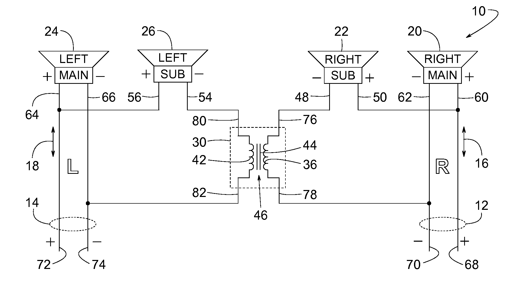
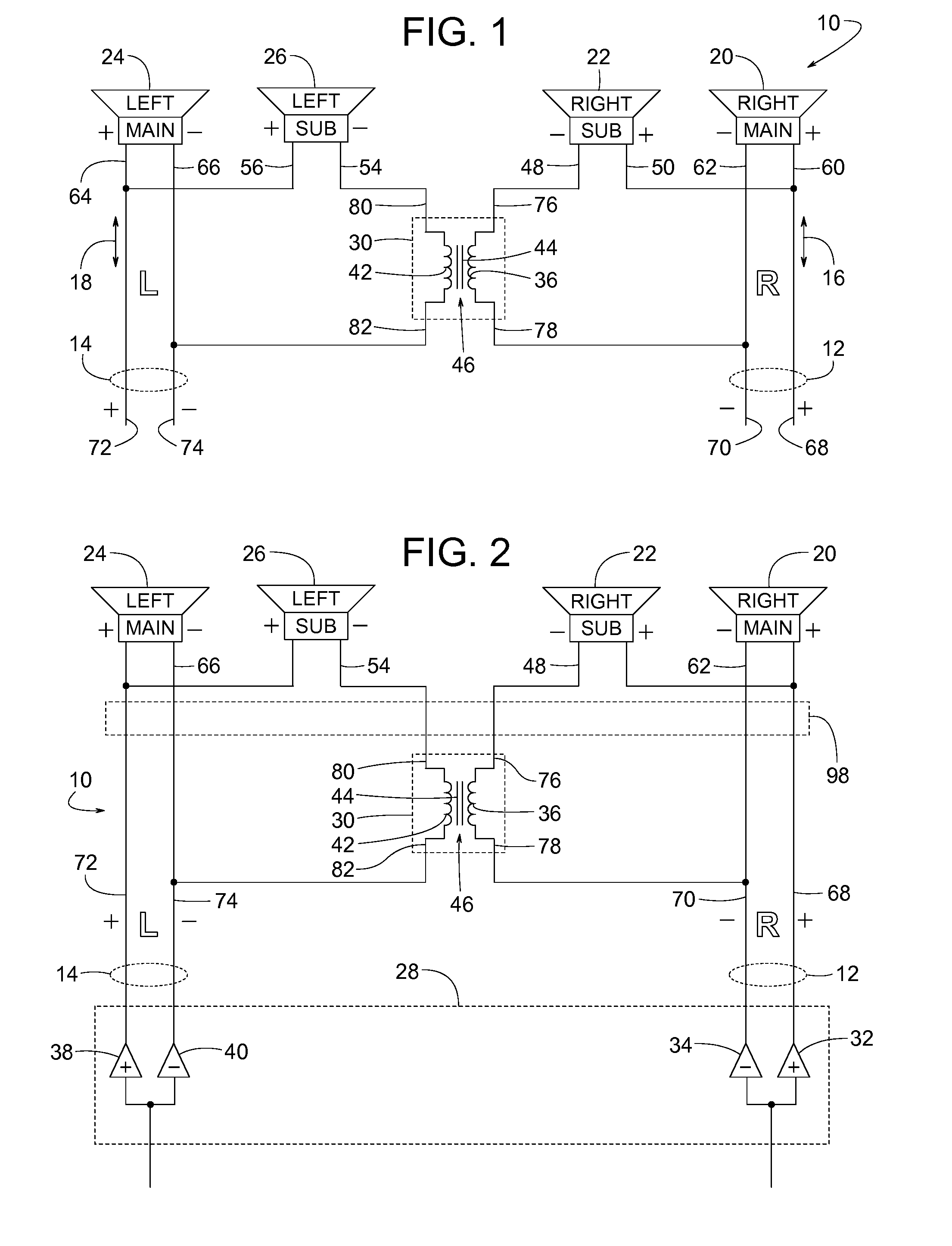
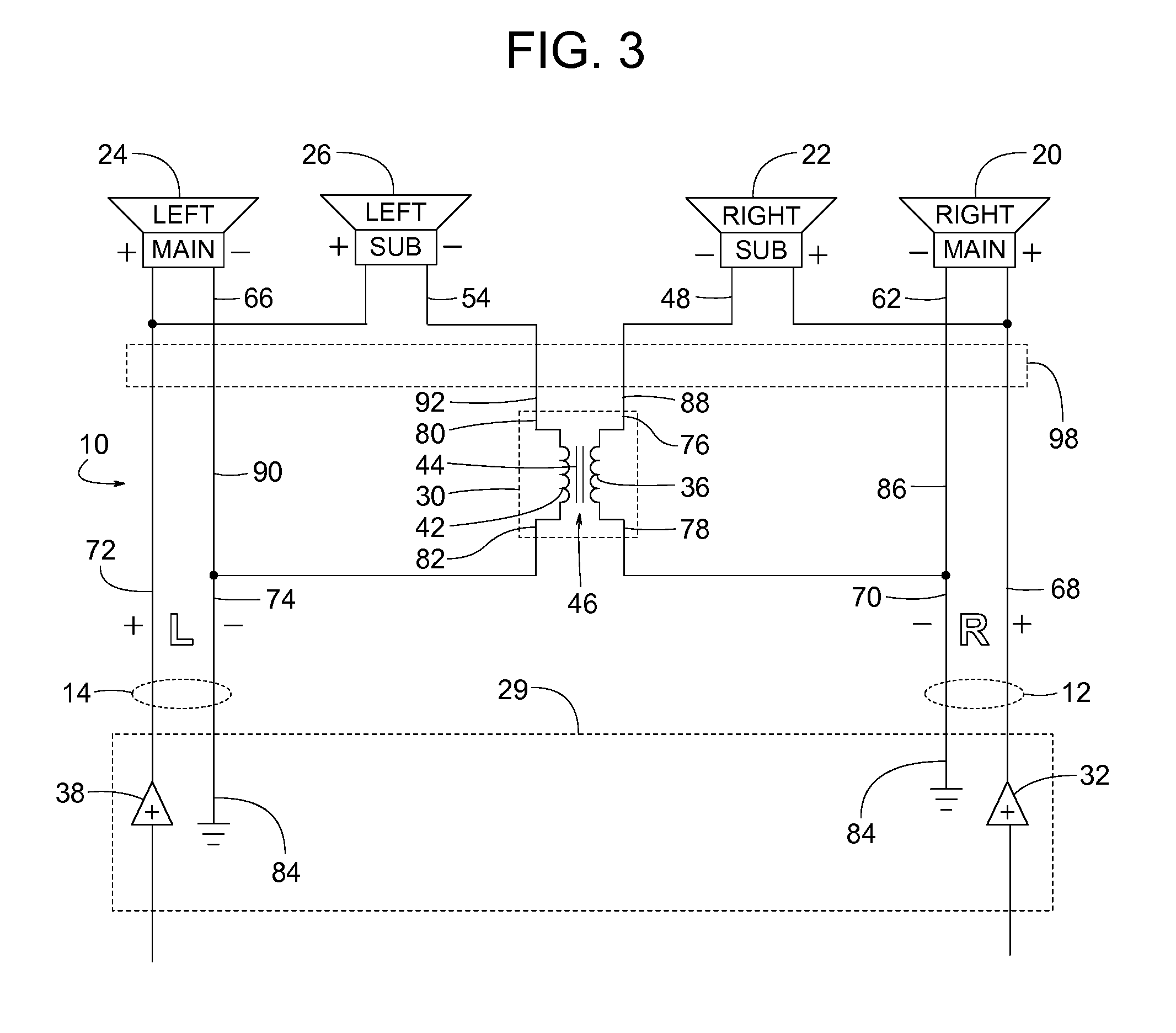
[0020]FIGS. 1-8 illustrate an example stereo loudspeaker system 10 having a right channel 12 and a left channel 14 that deliver an audio signal R 16 and an audio signal L 18 to right and left sets of speakers. In some examples, the right set of speakers includes a right main speaker 20 and a right sub-speaker 22, and the left set of speakers includes a left main speaker 24 and a left sub-speaker 26. FIG. 1 shows a basic electrical schematic of one example of system 10, FIG. 2 shows system 10 including an example bridge style amplifier system 28, FIG. 3 shows system 10 including an example non-bridge style amplifier system 29, FIGS. 4 and 5 show example audio signal flow patterns at different frequencies, and FIGS. 6, 7 and 8 show examples where multiple speakers of system 10 share the same acoustic volume within various enclosures.

[0021]To achieve the benefits and overcome the limitations of the loudspeaker systems disclosed in U.S. Pat. Nos. 4,489,432 and 4,638,505, both of which a...


PUM


Abstract

A stereo loudspeaker system with a right channel and a left channel respectively feeding R and L signals to four speakers (including a right main speaker, a right sub-speaker, a left main speaker and a left sub-speaker) includes a transformer that, depending on the frequency, magnetically couples or isolates the two channels at the right and left sub-speakers. At low frequencies, the transformer isolates the right channel from the left one so that the R signal goes primarily only to the two right speakers, and the L signal goes primarily only to the two left ones. At high frequencies, both the right and left main speakers still receive their respective R and L signals; however, the transformer's magnet coupling conveys a differential R-L signal to the right sub-speaker and a differential L-R signal to the left sub-speaker, thereby producing an expanded acoustic image and realistic ambient field.

Description

FIELD OF THE DISCLOSURE[0001]The present disclosure relates generally to loudspeaker systems and more specifically to stereo systems with two channels each having main and sub speakers.BACKGROUND[0002]Some stereo loudspeaker systems have right and left channels driving four speakers, wherein the four speakers include a pair of speakers on the right and another pair on the left. Each pair comprises a main speaker and an associated sub-speaker, so the system includes a right main speaker, a right sub-speaker, a left main speaker and a left sub-speaker. Examples of such systems are disclosed in U.S. Pat. Nos. 4,489,432 and 4,638,505, both of which are specifically incorporated herein by reference.[0003]In some cases, the right and left channels feed R and L signals to the right and left main speakers, respectively. In addition, at lower frequencies, R and L signals are applied respectively to the right and left sub-speakers as well. At certain higher frequencies, however, a differentia...

Claims


Application Information

Patent Timeline
Patent Type & Authority Patents(United States)
IPC IPC(8): H04R5/02
CPCH04R5/02H04R1/26H04R3/12H04R5/04H04R2430/03
Inventor JOHNSTON, ROBERT G.
Owner JOHNSTON ROBERT G
Why Eureka
Try Eureka