
Radiographic system and control method thereof

a technology of a radiographic system and a control method, applied in the direction of radiation beam directing means, instruments, applications, etc., can solve the problems of poor stability of the irradiation angle of x-rays in the tomosynthesis imaging of changing the dose of x-rays, and achieve the effect of improving the balance of the densities of the detection field and high image quality

Inactive Publication Date: 2015-07-07
FUJIFILM CORP
View PDF12 Cites 11 Cited by
  • Summary
  • Abstract
  • Description
  • Claims
  • Application Information

AI Technical Summary

Benefits of technology

[0007]In the radiographic systems described in JP2000-501552T and JP2008-253555A, the variation in thickness of a subject is predicted on the basis of the irradiation angle of X-rays. However, the variation in thickness of a subject differs depending on radiographing sites, and sites in which the thickness greatly varies with a slight difference of the irradiation angle or sites in which the thickness hardly varies with a slight difference of the irradiation angle exist. Accordingly, the tomosynthesis imaging of changing the dose of X-rays on the basis of the irradiation angle of X-rays has poor stability, from the viewpoint of making the densities of detection fields of respective images uniform.
[0018]According to the present invention, since the AEC is performed for each radiographing operation of the tomosynthesis imaging, it is possible to improve the balance of the densities of the detection fields of a series of radiological images acquired for each radiographing and thus to acquire a tomographic image with high image quality. Since the AEC of each radiographing uses the detection field set depending on the irradiation position of the radiation source, it is possible to perform a radiographing operation with appropriate densities of the detection fields of a series of radiological images. Since the detection field is automatically set on the basis of the irradiation position of the radiation source, it is possible to simply and rapidly set the detection field.

Problems solved by technology

Accordingly, the tomosynthesis imaging of changing the dose of X-rays on the basis of the irradiation angle of X-rays has poor stability, from the viewpoint of making the densities of detection fields of respective images uniform.

Method used


Image

  • Radiographic system and control method thereof
  • Radiographic system and control method thereof
  • Radiographic system and control method thereof

Examples


Embodiment Construction

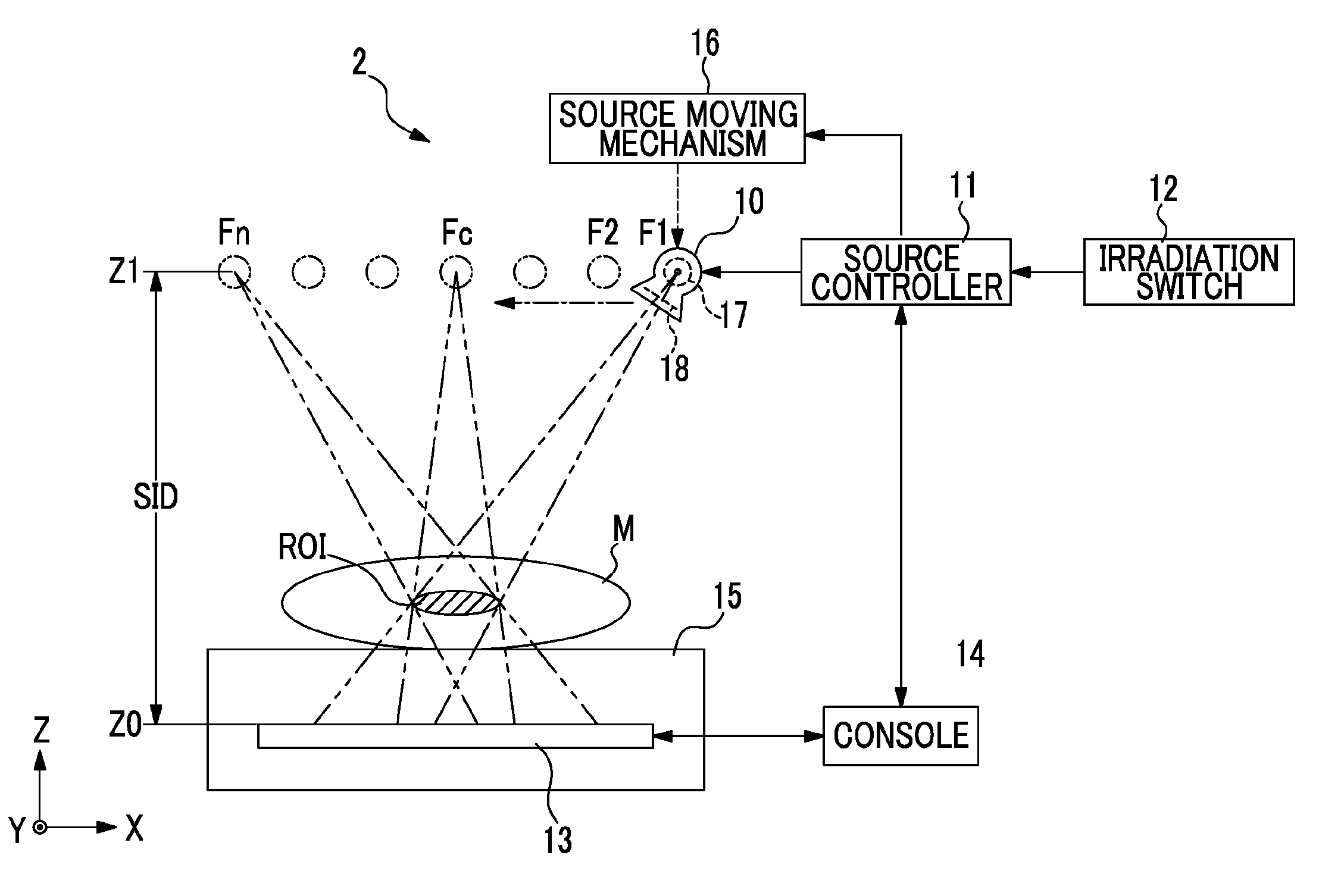
[0036]In FIG. 1, a radiographic system 2 includes an X-ray source 10, a radiography platform 15 that is disposed to face the X-ray source 10 and on which a subject M is placed, an electronic cassette 13 that detects X-rays passing through the subject M and outputs an X-ray image, a source moving mechanism 16 that causes the X-ray source 10 to move to plural predetermined positions, a source controller 11 that controls the X-ray source 10 to irradiate the subject M on the electronic cassette 13 with X-rays when the X-ray source 10 reaches a predetermined position (hereinafter, referred to as an irradiation position), and a console 14 that controls the electronic cassette 13 and that reconstructs a series of X-ray images sequentially transmitted from the electronic cassette 13 to generate a tomographic image. A tomographic image generating unit constitutes a part of the console 14 and a radiological image detector constitutes a part of the electronic cassette 13.

[0037]The radiographic...


PUM


Abstract

A detection field setting unit of a console sets a detection field of detection pixels of an electronic cassette which are used to detect the dose of X-rays passing through a subject so as to correspond to each irradiation position on the basis of irradiation positions of an X-ray source set by a driving condition setting unit and ROI information such as the position and the size of a region of interest (ROI) of the subject M input through an input device and the height thereof from a radiography platform. The electronic cassette performs an automatic exposure control of detecting the dose of X-rays by the use of the detection pixels in the detection field set by the detection field setting unit of the console and automatically controlling the irradiation dose of X-rays on the basis of the detected dose, when performing a radiographing operation at the irradiation positions.

Description

BACKGROUND OF THE INVENTION[0001]1. Field of the Invention[0002]The present invention relates to a radiographic system that radiographs a tomographic image using radiation and a control method of the radiographic system.[0003]2. Description of the Related Art[0004]In the medical fields, radiographic systems using radiation such as X-rays are known. A radiographic system includes an X-ray generator including an X-ray source generating X-rays and an X-ray imaging apparatus receiving X-rays and capturing an X-ray image. As an X-ray imaging apparatus, an X-ray image detector using as a detection panel a flat panel detector (FPD) in which pixels accumulating signal charges corresponding to the dose of X-rays are arranged in a matrix shape has been widely spread. The FPD accumulates signal charges in the respective pixels and converts the accumulated signal charges into a voltage signal through the use of a signal processing circuit, whereby an X-ray image representing image information o...

Claims


Application Information

Patent Timeline
Patent Type & Authority Patents(United States)
IPC IPC(8): A61B6/08A61B6/00A61B6/03A61B6/02
CPCA61B6/032A61B6/548A61B6/025A61B6/4283A61B6/5288A61B6/542A61B6/4233
Inventor KOISHI, TAKESHI
Owner FUJIFILM CORP
Learn More