Reciprocating power tool

a technology of power tools and drive mechanisms, which is applied in the direction of power-driven reciprocating saws, portable power-driven tools, power-driven drilling machines, etc., can solve the problems of reducing the notch effect and flaring of the connection, reducing the impact and wear of early power tools, and not easy to penetrate the urethane bed

Active Publication Date: 2015-07-07
CRYSTAL GLASS CANADA
View PDF48 Cites 16 Cited by
  • Summary
  • Abstract
  • Description
  • Claims
  • Application Information

AI Technical Summary

Benefits of technology

[0037]The rectangular cross sectional portions of the drive shaft assist in accommodating the high torsional stresses placed on the drive shaft with a high impact tool, while providing secure locking into the front end and rear end bushings which in turn are formed to mate with the rectangular cross sectional sections of the drive shaft.
[0038]The reciprocating power tool may be adapted such that one or more of the drive shaft, crown gear and drive pin are counterbalanced to reduce vibration caused by reciprocating movement of the drive shaft. In one embodiment, a counterweight is formed on a first half portion of the crown gear. In this embodiment, the eccentric pin is located in a second half portion of the crown gear diametrically opposite to the counterweight. These features reduce the vibrational forces of a high impact, high speed tool (typically 2800-3600 strokes per minute) having a short linear stroke (typically 5-15 mm).
[0040]The eccentric pin may include a collar bushing adapted for rotation on the eccentric pin, the collar bushing being formed of a wear resistive material, and the collar bushing forming an outwardly extending lip at a lower end proximate the base section of drive pin. In this embodiment, the drive shaft forms a recess around an outer periphery of the slot adapted to receive and retain the lip of the collar bushing. The collar bushing accommodates the high impact and wear which would otherwise be transferred to the eccentric pin due to torque and loads on the drive shaft, or wear on the drive shaft bushings. The collar bushing can be replaced after a wear cycle without causing excessive wear to other components of the drive mechanism.
[0041]The front end bushing for the drive shaft may be formed as a split bushing, for ease of assembly. The drive shaft may have a cylindrical section (i.e., round in transverse cross section) forward of the front end bushing, and the front end may be adapted to be received and connected in a socket type connection within one or more stepped counterbores formed in a rear connecting end of the external shaft. In this embodiment, the external shaft may have a cylindrical section (i.e., round in transverse cross section) at its rear end for attachment to the drive shaft. This embodiment reduces the notch effect and flaring of the connection between the drive shaft and the external shaft. The connection between the shafts may be provided at a point internal of the tool (i.e., rearwardly of a front nose cone on the housing), or external of the tool (i.e., forward of the nose cone).

Problems solved by technology

The urethane bed is hard and tough and not easily penetrated.
In use, these early power tools were characterized by several problems.
More particularly:Cutting with them was slow.The depth and width of the cut were small, requiring a great many cuts to complete the job.Typically it would take about 15-20 minutes to cut the windshield free.Using the prior art assemblies was laborious.
The installer would have to apply a sideways pull to these tools, particularly when cutting along the horizontal legs of the bed.It was common to crack the glass when first penetrating the bed.
This could leave broken glass on the dash and elsewhere, which was undesirable.The cuts made by the tools were shallow.
This meant that at the corners, where the bed width was greatest, it would take prolonged cutting to complete severing the bed.
In practice, the installer would revert to using a hand knife at the corners or would break off the glass at the corners and have to later complete the cut by hand of the corner urethane with its embedded glass.In the course of hand cutting the corners, installers would commonly press hard with their head against the windshield to assist in cutting, leading to neck injuries.The cut surface produced by the blades of these powered tools was irregular, tagged and undulating.
This was undesirable as the newly extruded bead would in part reproduce this underlying irregularity and the new windshield would then not seat flush against the bed surface.
This could lead to a poor seal and subsequent leaking.The electric motor-driven tools of the prior art were generally bulky and difficult to work with in the confined space of the apex between the vehicle dashboard and the inside surface of the windshield.The prior art blades were fragile and expensive; breakage was a problem.It was necessary to use soapy water as a coolant and lubricant for the narrow, rapidly moving blades.
After the cut was complete, the cut surface needed to be carefully washed to remove soap, as it was detrimental to getting a good bond when new urethane was laid on to the old bed.
While the above Ogston assembly was a marked improvement over many of the other prior art devices, it presented its own unique issues, including:The sharp corner edges at the front end of the blade could damage either or both of the pinch weld of the vehicle holding the windshield, or to the dashboard or upholstery of the vehicle.Due to the extreme flexing requirements for the blade during use against the windshield, including twisting motions, the blade could break at the stress point between the bell shaped side edges of the blade and the straight shank side edges where the blade connected to the shaft.
As well, the shaft could break at the stress point at the connection to the blade.Penetration of the urethane bed, particularly at the corners where the bed is deepest, was sometimes still difficult.Cutting around the corners of the windshield presented some difficulty, with the sharp corners limiting movement around the corner.Cutting was primarily in the vertical (i.e., forward) direction, as the front end of the blade cut into the urethane bed.
The bell-shaped blades could not be simply elongated to accommodate the needed deeper penetration without the blade becoming too fragile when flexed, i.e., if elongated beyond about 7.75 inches, the bell-shaped blades would break at their stress point (i.e., where the blade side edges joined to the shank).The air gun, while suitable for some applications, did not meet all customer needs.
However, the reciprocating power units used to drive the blades still have many of the problems outlined above, leading to breakage of the external shaft at its forward end where it connects to the blade and / or breakage at the connection of the external shaft to the internal drive shaft of the power tool.
As well, the reciprocating drive mechanism used in the power tool were often a simple adaption of a reciprocating saw drive mechanism, which is not designed for the high impact, short linear stroke and loading for the complete cycle needed to drive a windshield removal tool, leading to tool failure.

Method used


Image

  • Reciprocating power tool
  • Reciprocating power tool
  • Reciprocating power tool

Examples


Embodiment Construction

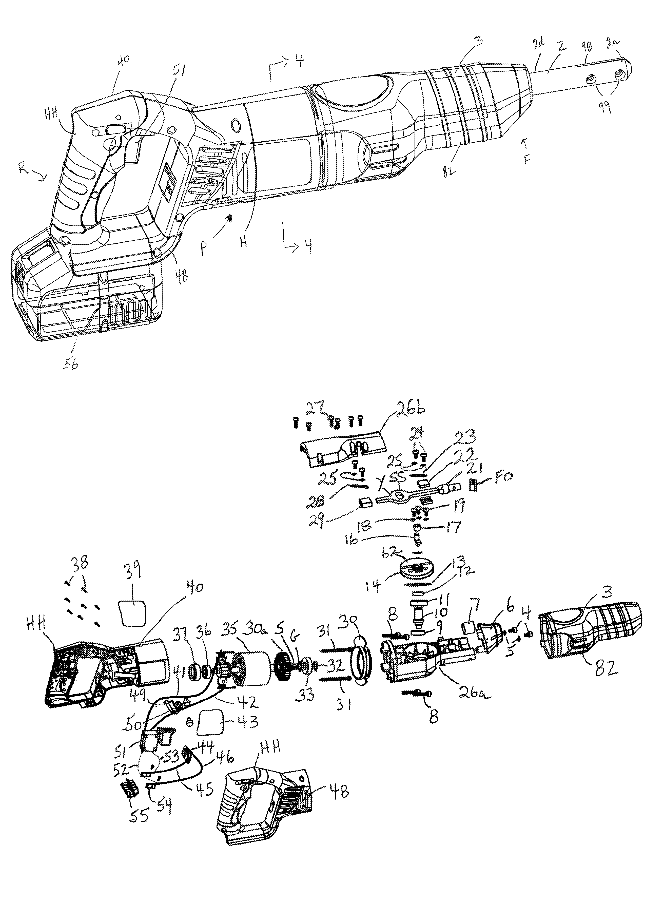
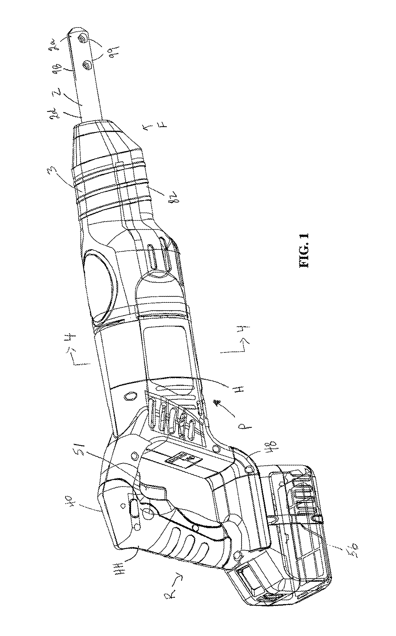
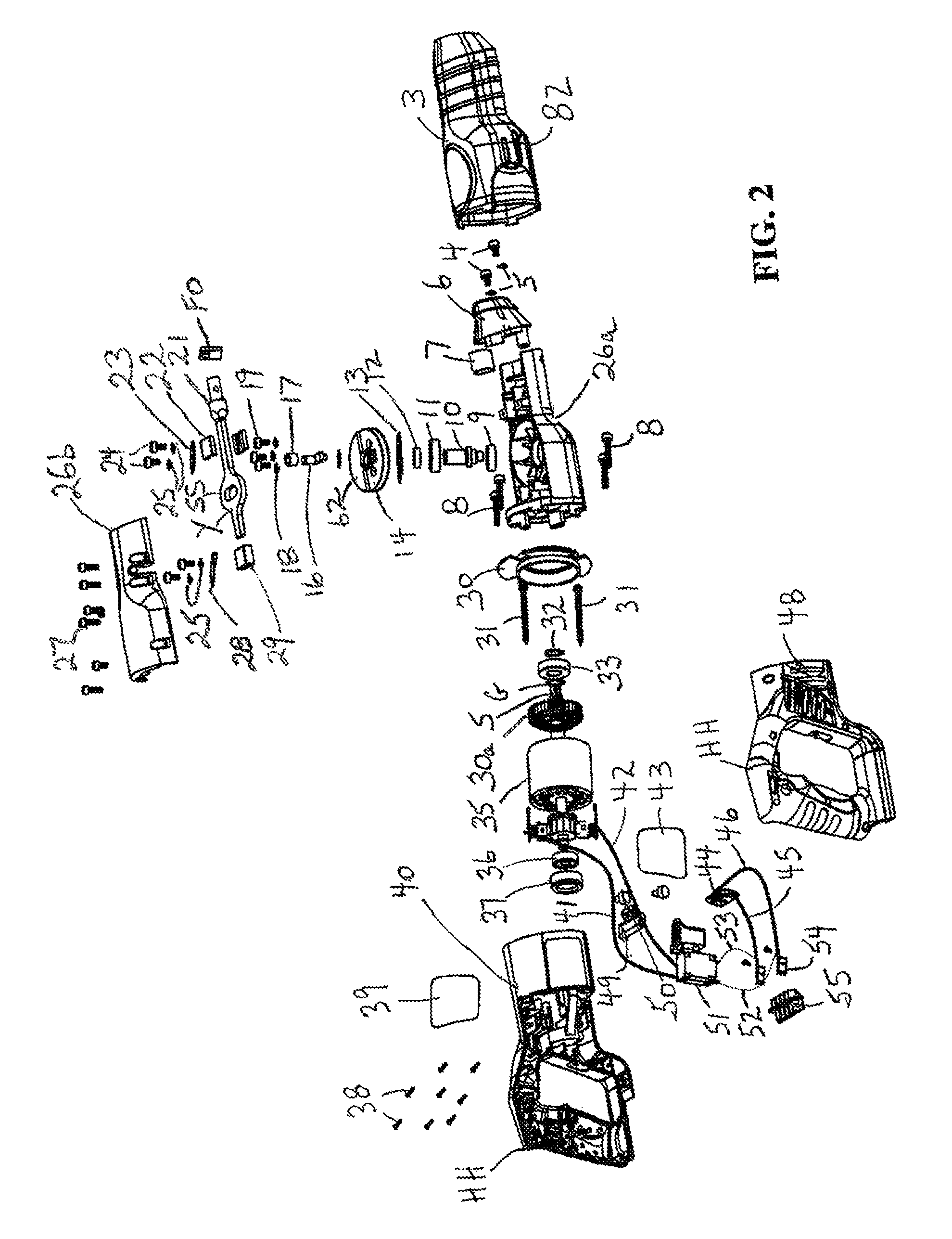
[0063]Having reference to FIGS. 1-13, exemplary embodiments of the power tool P and its components are shown, with FIGS. 1 and 4 showing the tool in connected views, and FIGS. 2 and 3 showing the tool in exploded views. The tool P is shown to have a front or forward end F, and a rear or rearward end R. Components of the drive mechanism D are shown in greater detail in FIGS. 5-9. A removable nose cone 6 may be included, as shown in FIGS. 10A-F and 12A-E to accommodate a nose cone bushing 7. Alternate embodiments of an internal drive shaft are shown in FIGS. 5A, 5B; 6A, 6B; and 11A, 11B. An external shaft adapted to connect between the drive shaft of FIGS. 11A, 11B and to a windshield removal blade is shown in FIGS. 13A-13C.

[0064]The power tool P includes a housing H, including a left body 40 and a right body 48 connected by screws 38 and optionally providing left and right label plates 39 and 43. A handle HH is formed at the rear of the housing H, with a variable speed trigger switch...


PUM

PropertyMeasurementUnit
stroke lengthaaaaaaaaaa
rated voltageaaaaaaaaaa

Abstract

A reciprocating power tool and drive mechanism with a drive shaft mounted for reciprocating movement relative to a housing along a center longitudinal axis of the drive shaft. The drive shaft has a front end adapted to attach to an external shaft or tool attachment, a rear end, and a slot oriented perpendicular to the center longitudinal axis of the drive shaft between the front and rear ends. A motor driven shaft imparts rotary movement to a pinion gear, which meshes with a crown gear to impart rotary motion to the crown gear about its center axis. A drive pin connected to the crown gear has an eccentric pin eccentrically offset relative to the center axis of the crown gear for engagement in the slot of the drive shaft so as to impart the reciprocating movement to the drive shaft on rotation of the crown gear.

Description

CROSS-REFERENCE TO RELATED APPLICATION[0001]This application claims priority from U.S. Provisional Patent Application No. 61 / 487,605 filed May 18, 2011, which is incorporated by reference herein to the extent that there is no inconsistency with the present disclosure.BACKGROUND OF THE INVENTION[0002]This invention relates to a reciprocating power tool and drive mechanism for same, such as for a automobile windshield or other glazing removal operations, which involve cutting a urethane bed around the windshield or glass perimeter and separating the glass or windshield from a vehicle.[0003]In the process of securing a glass windshield to a new car or truck, the manufacturer first extrudes a bead or “bed” of urethane onto the “pinch weld” extending around the perimeter of the window opening. The urethane bed bonds to the pinch weld surface. The glass windshield then is seated on the bed and bonds to it, forming a liquid-tight seal. The urethane bed is hard and tough and not easily pene...

Claims


Application Information

Patent Timeline
Patent Type & Authority Patents(United States)
IPC IPC(8): B27B19/04B23D51/16B23D51/10B25F5/02B62B7/00
CPCB62B7/00B23D51/10B23D51/16B25F5/02B26B7/00
Inventor MIDDLETON, SCOTT D.PARNALL, WINSTON HAROLDOGSTON, ALFRED JOHN
Owner CRYSTAL GLASS CANADA
Why Eureka
Try Eureka