System and method for dynamic aeroelastic control
a dynamic aeroelastic and control system technology, applied in the field of structural monitoring, can solve the problems of reducing the effectiveness of multi-mode vibration suppression, affecting safety and performance, and not giving an accurate reflection of the true structural state of the aircraft, so as to reduce drag, reduce flutter, and maximize fuel efficiency
- Summary
- Abstract
- Description
- Claims
- Application Information
AI Technical Summary
Benefits of technology
Problems solved by technology
Method used
Image

Examples
example 1
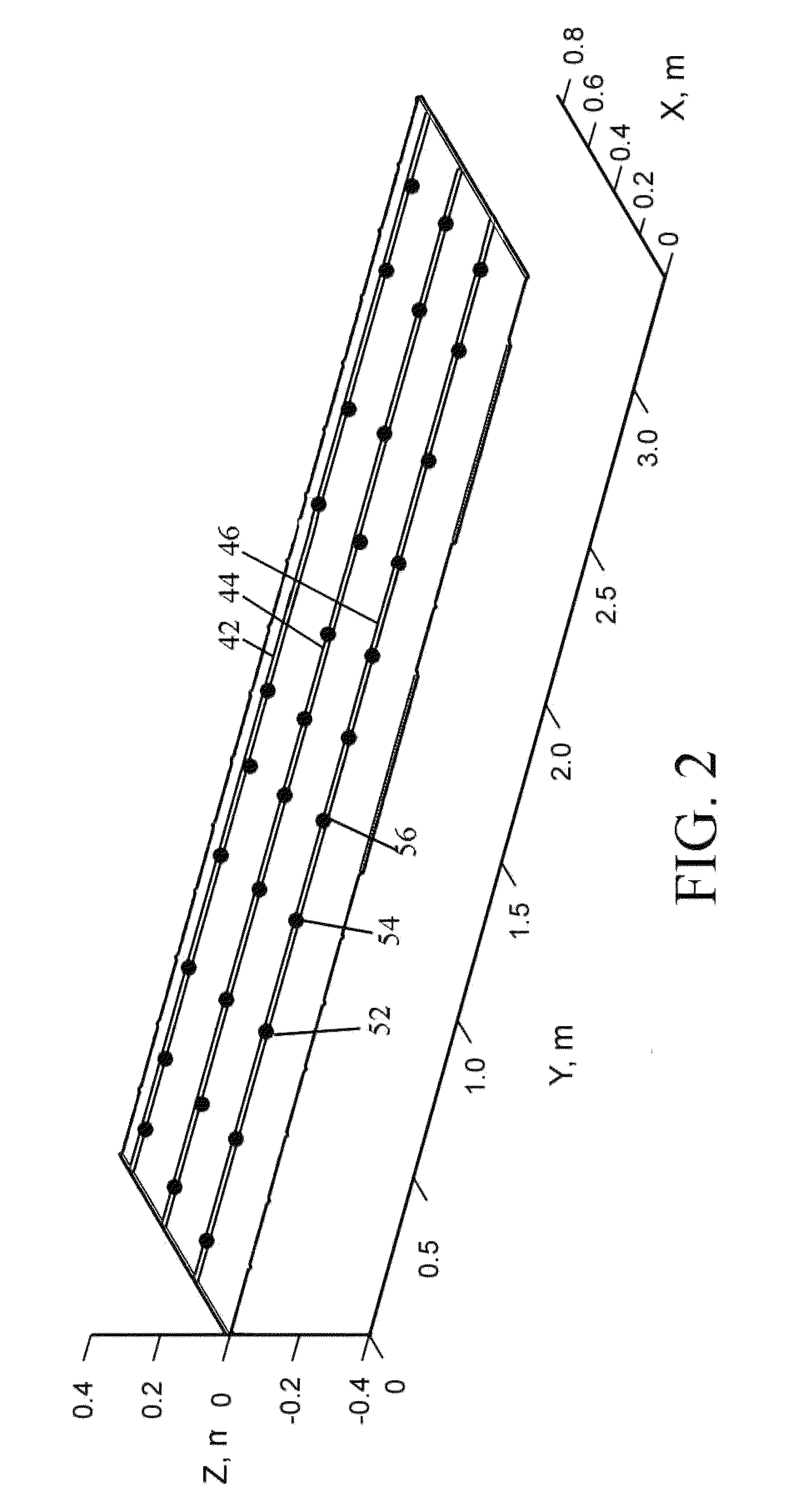
[0087]The above-described system has been verified with a simple FEM model of a wing developed using MATLAB / Simulink™. The wing model allowed the user to input aspects such as wing span and chord, as well as number and location of control surfaces. The finite element model was coupled with an unsteady aerodynamics model and gust model captured by Rational Function Approximations (RFAs) of the generalized forces found through frequency based linear aerodynamic methods. Fighter aircraft type actuators were utilized for dynamic control surface simulation. State space models were formed and a simulated modal filtering system was designed. The state space models were also utilized for control design. The system was implemented with an array of fiber optics with FBG sensors. The wing model was structurally simple.
example 2
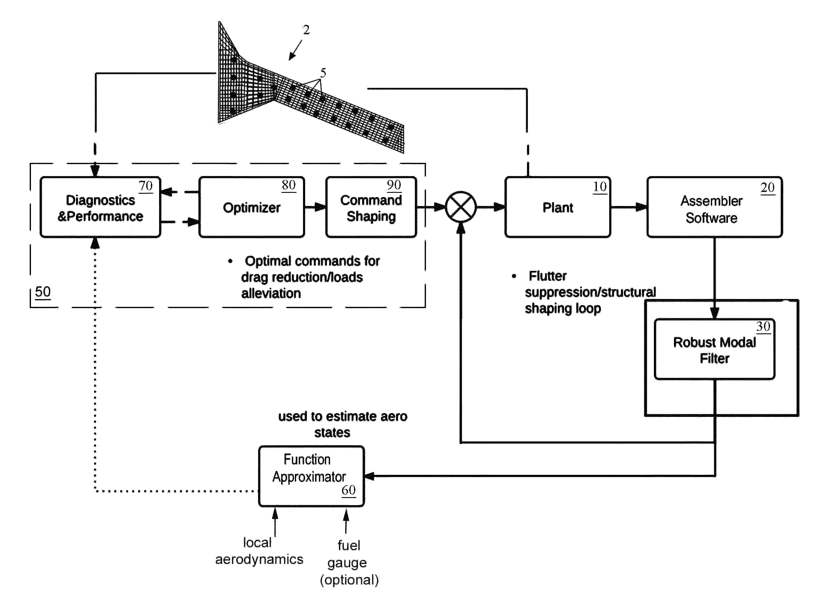
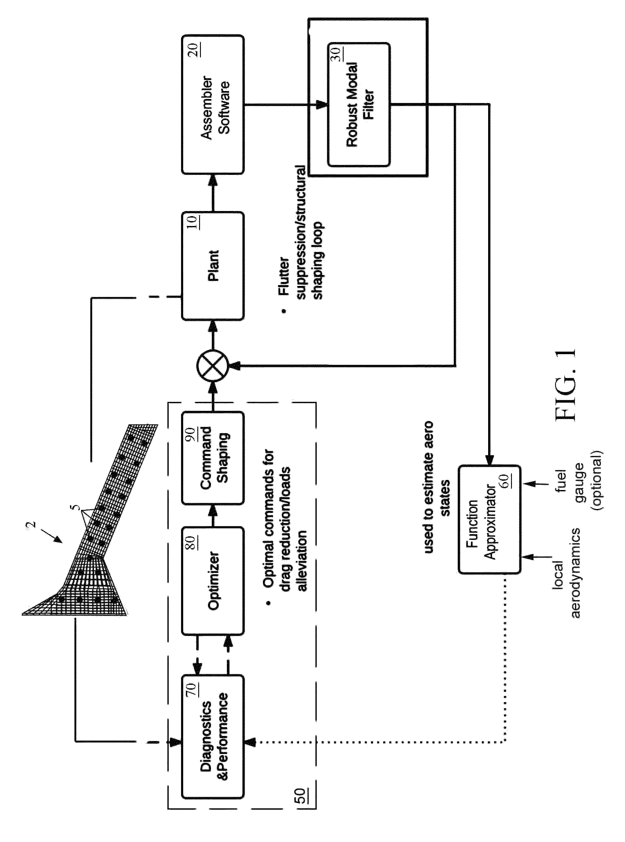
[0088]The above-described system has been verified with a complex X-56A aircraft model as shown in FIG. 3. The design of the Command Shaping Module 90 (from FIG. 1) is shown in FIG. 4. This architecture assumes a virtual deformation control architecture with modal reference tracking. Since deformation is directly related to modal displacements, the significant modal displacements are commanded directly, thereby leading to deformation changes in the vehicle. This is what is referred to by virtual deformation control architecture. Note that the FOS simulation and FOS Noice Simulations at right would be replaced by the FOSS Sensing System 2 of FIG. 1 in a real-aircraft implementation.
[0089]Identification of significant modes in an aircraft structure is similar to that for a wing model. V-g and V-f plots or equivalent may be used to determine interacting modal coordinates, and modal coordinates must be selected for feedback which contribute to flutter, modal vibration and are within the...
PUM
 Abstract
Description
Claims
Application Information
 - R&D
- Intellectual Property
- Life Sciences
- Materials
- Tech Scout
- Unparalleled Data Quality
- Higher Quality Content
- 60% Fewer Hallucinations
Browse by: Latest US Patents, China's latest patents, Technical Efficacy Thesaurus, Application Domain, Technology Topic, Popular Technical Reports.
© 2025 PatSnap. All rights reserved.Legal|Privacy policy|Modern Slavery Act Transparency Statement|Sitemap|About US| Contact US: help@patsnap.com