Rotorcraft control system

a control system and rotorcraft technology, applied in the field of rotorcraft, can solve the problems of inability to perform hovering flight, inability to vertical flight, and complicated technical details, and achieve the effect of increasing the power needed and saving weight and cos

Active Publication Date: 2012-05-01
EUROCOPTER
View PDF24 Cites 60 Cited by
  • Summary
  • Abstract
  • Description
  • Claims
  • Application Information

AI Technical Summary

Benefits of technology

[0070]In a preferred embodiment, in cruising flight, the longitudinal cyclic pitch of the rotor is controlled so as keep the fuselage attitude at a pitch angle (or longitudinal trim angle) that is equal to the slope of the flightpath so as to reduce to zero the angle of incidence of the fuselage relative to air, thereby minimizing drag from said fuselage. Consequently, and during level cruising flight, the longitudinal trim of the hybrid helicopter is maintained at a value of zero. Furthermore, and advantageously, the pitching moment of the fuselage is also adjusted by operating at least one movable pitch-control surface fitted to the horizontal stabilizer, e.g. by using an electric actuator, so as to compensate for any offset of the center of gravity of said hybrid helicopter: this adjustment is obtained in principle when the bending moment acting on the rotor mast relative to the pitch axis is zero, e.g. as measured by strain gauges.
[0071]It is advantageous to be able to adjust or even eliminate the pitching moment of the fuselage since firstly that acts directly on the bending moment in the rotor mast and thus on the fatigue stress thereof, and secondly it leads to overall balance of the vehicle as a result of the way power is distributed between the propellers and the rotor. This distribution has an influence on the overall power balance since the propellers and the rotor present different respective efficiencies.
[0072]During this operation, the distribution of power between the rotor and the propellers can vary significantly as a function of the angle of inclination of the rotor disk because of its contribution to variations in total drag and in the propulsion of the vehicle. By way of example, the power needed in high-speed cruising flight is due mainly to the parasitic drag of the vehicle. At 140 kt, parasitic power represents approximately 50% of the total power requirement and can reach 75% at 220 kt, i.e. three times the power needed for lift. Efficiency at high speed thus depends on minimizing parasitic drag, whence the advantage of controlling the longitudinal trim of said hybrid helicopter.
[0092]Thus, the rotor delivers part of the lift to the hybrid helicopter in cruising flight, possibly also with a small contribution to propulsion or traction forces (acting as a helicopter) or without any contribution to drag (acting as an autogyro). These conditions of operation thus lead to less power being delivered for the purpose of enabling the rotor to provide traction. It should be observed that a small contribution to propulsion forces is made by the rotor disk being tilted towards the front of the vehicle by a small amount only. This process degrades the lift / drag ratio of the rotor very little so it is consequently more advantageous in terms of power balance than an additional demand for thrust delivered by the propeller(s).
[0106]These various functions described above are made possible by a mechanical interconnection system suitable for transmitting power. Such a system must be capable of transmitting high levels of torque, in particular because of the high level of power absorbed and the relatively low speed of rotation of the rotor. This requires large reduction ratios in speed of rotation between the various components of the drive system, while maintaining a weight that is as small as possible and ensuring good endurance and good overall safety.

Problems solved by technology

That configuration is not capable of vertical flight unless the rotor is initially set into rotation by an auxiliary device enabling the rotor to be caused to rotate faster: an autogyro is therefore not capable of performing hovering flight but only of moving upwards or downwards on flightpaths having very steep slopes.
Of those various forms of rotorcraft, the helicopter is the simplest, and as a result it has been successful in spite of having a maximum horizontal speed in translation of about 300 kilometers per hour (km / h) which is small and less than that which can be envisaged by compound rotorcraft and convertible type formulae that are technically more complex and more expensive.
Under such conditions, improvements to the above formulae have been proposed for increasing rotorcraft performance, but without that leading to solutions that are complicated, difficult to manufacture and to operate, and consequently expensive.
A device of that type therefore implies additional weight and cost, and constitutes a penalty in terms of safety.Stopping the rotor and reconfiguring it, e.g. a three-blade rotor stopped in a particular configuration serves as a swept-back wing for flight at a high forward speed, or indeed, after stopping, it is possible to envisage folding the rotor over the fuselage during a rotorcraft-to-airplane transition stage.
It can be understood that those solutions complicate the technical implementation and contribute to increasing weight, and thus to increasing installed power and consequently expense, but without that achieving an optimized vehicle.

Method used


Image

  • Rotorcraft control system
  • Rotorcraft control system
  • Rotorcraft control system

Examples


Embodiment Construction

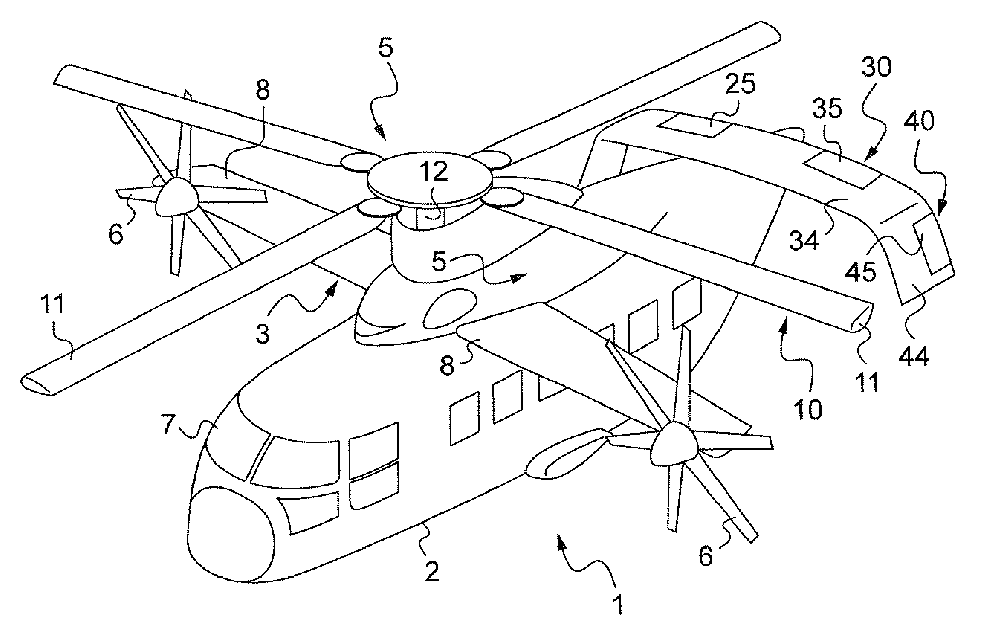
[0123]In the meaning of the present application, the term “hybrid helicopter” means a rotorcraft fitted with one or more thrusters, with regulation adapted both to the operation of the rotor and to the operation of the propellers.

[0124]Unless specified to the contrary, implicitly or explicitly, the term “rotor” designates a rotary wing of the rotorcraft.

[0125]Unless specified to the contrary, implicitly or explicitly, any element present in two or more distinct figures is given the same reference in each of them.

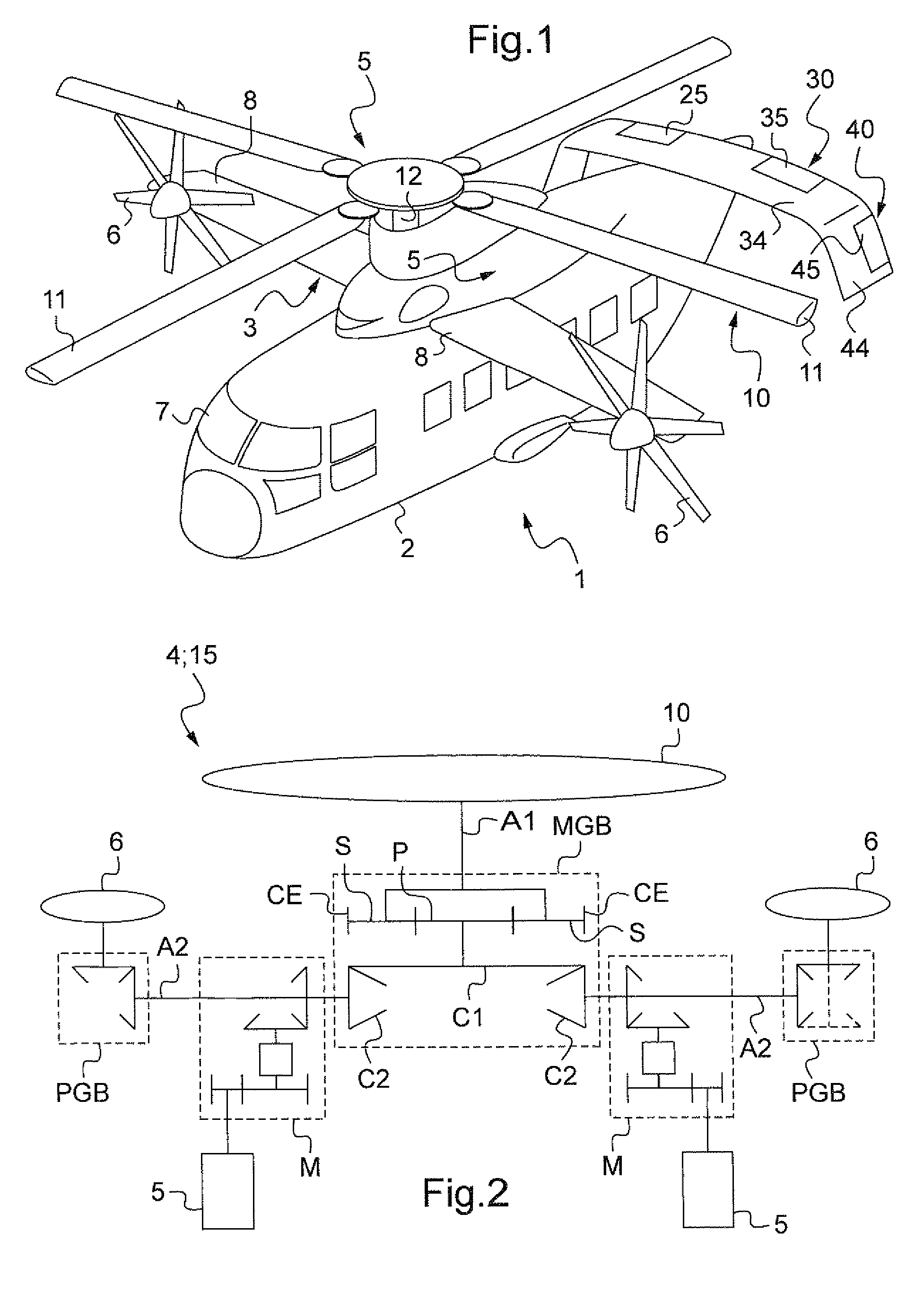
[0126]With reference to FIG. 1 in particular, the hybrid helicopter 1 comprises a fuselage 2 with a cockpit 7 at the front thereof, a rotor 10 for driving blades 11 in rotation by means firstly of two turbine engines 5 disposed on top of the fuselage 2 (not visible in FIG. 1 because of the presence of fairing), on either side of the longitudinal plane of symmetry of the rotorcraft, and secondly a main first gearbox MGB (not shown in FIG. 1).

[0127]Furthermore, the hybrid heli...


PUM


Abstract

A system (100) for controlling a rotorcraft (1) including a rotor (10), at least one variable-pitch propulsion propeller (6L, 6R), and a motor (5) for driving the rotor and the propeller(s), the system includes:a member (101, 101A, 102, 103, 104) for generating a propeller pitch setpoint (θp*+θd*, θp*−θd*) as a function at least of a thrust variation command (TCL);a member (105, 105A) for generating a setpoint (RPM*) for the drive speed (RPM) of the rotor and the propeller(s), as a function at least of the travel speed (VTAS) of the rotorcraft; anda member (106) for generating a setpoint (NG*) for the engine speed as a function at least of the thrust command (TCL), of the drive speed setpoint (RTM*), and of a rotor collective pitch command (θ0).

Description

[0001]The present invention relates to a rotorcraft and to a system for controlling (i.e. regulating or piloting) engine members of the rotorcraft.BACKGROUND OF THE INVENTION[0002]The term rotorcraft is used to designate an aircraft in which all or some of its lift is provided by one or more propellers of substantially vertical axis and large diameter, referred to as rotors or a rotary wing.[0003]There are several distinct types in category of rotorcraft.[0004]Firstly there is the helicopter in which at least one main rotor driven by a suitable power plant provides both lift and propulsion. A helicopter is capable of hovering flight, remaining at a fixed point in three dimensions, and it can take off and land vertically, and it can move in any direction (forwards, rearwards, sideways, upwards, downwards).[0005]Then there is the autogyro (first made by La Cierva) which is a rotorcraft in which the rotor does not receive power, but rotates in autorotation under the effect of the speed...

Claims


Application Information

Patent Timeline
Patent Type & Authority Patents(United States)
IPC IPC(8): G01C23/00
CPCB64C27/22G05D1/0858
Inventor ROESCH, PHILIPPE
Owner EUROCOPTER
Why Eureka
Try Eureka