Method for producing formic acid by CO2 hydrogenation
a technology of hydrogenation and formic acid, which is applied in the preparation of organic compounds/hydrides/coordination complexes, physical/chemical process catalysts, carboxylic compound preparations, etc., can solve the problems of substantially the same problems, unattractive previous methods, and inability to thermodynamically achieve the effect of a single reaction
- Summary
- Abstract
- Description
- Claims
- Application Information
AI Technical Summary
Benefits of technology
Problems solved by technology
Method used
Image

Examples
example i
[0061]The invention will be analyzed on the basis of Example I, which is to be understood purely as an example.
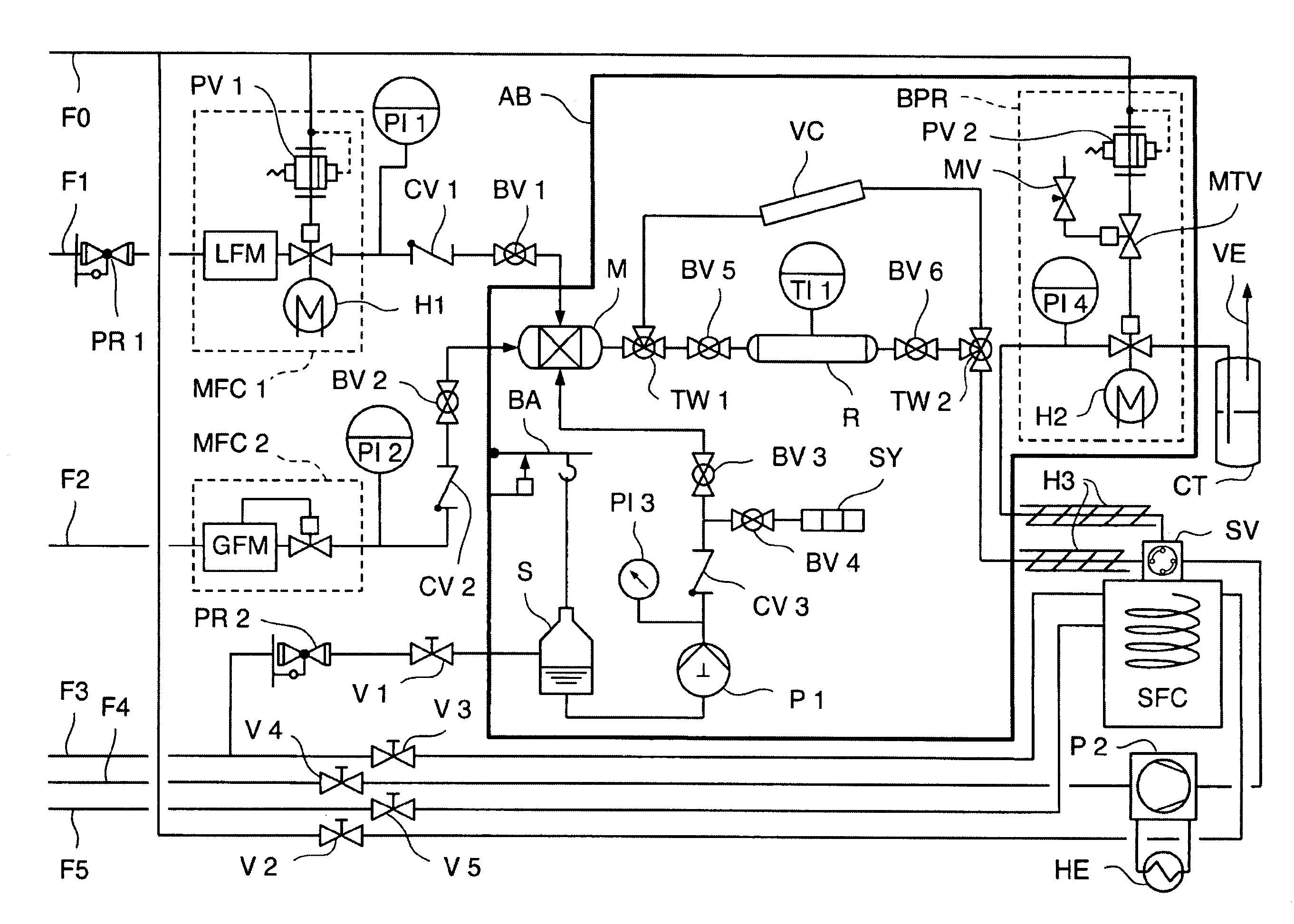
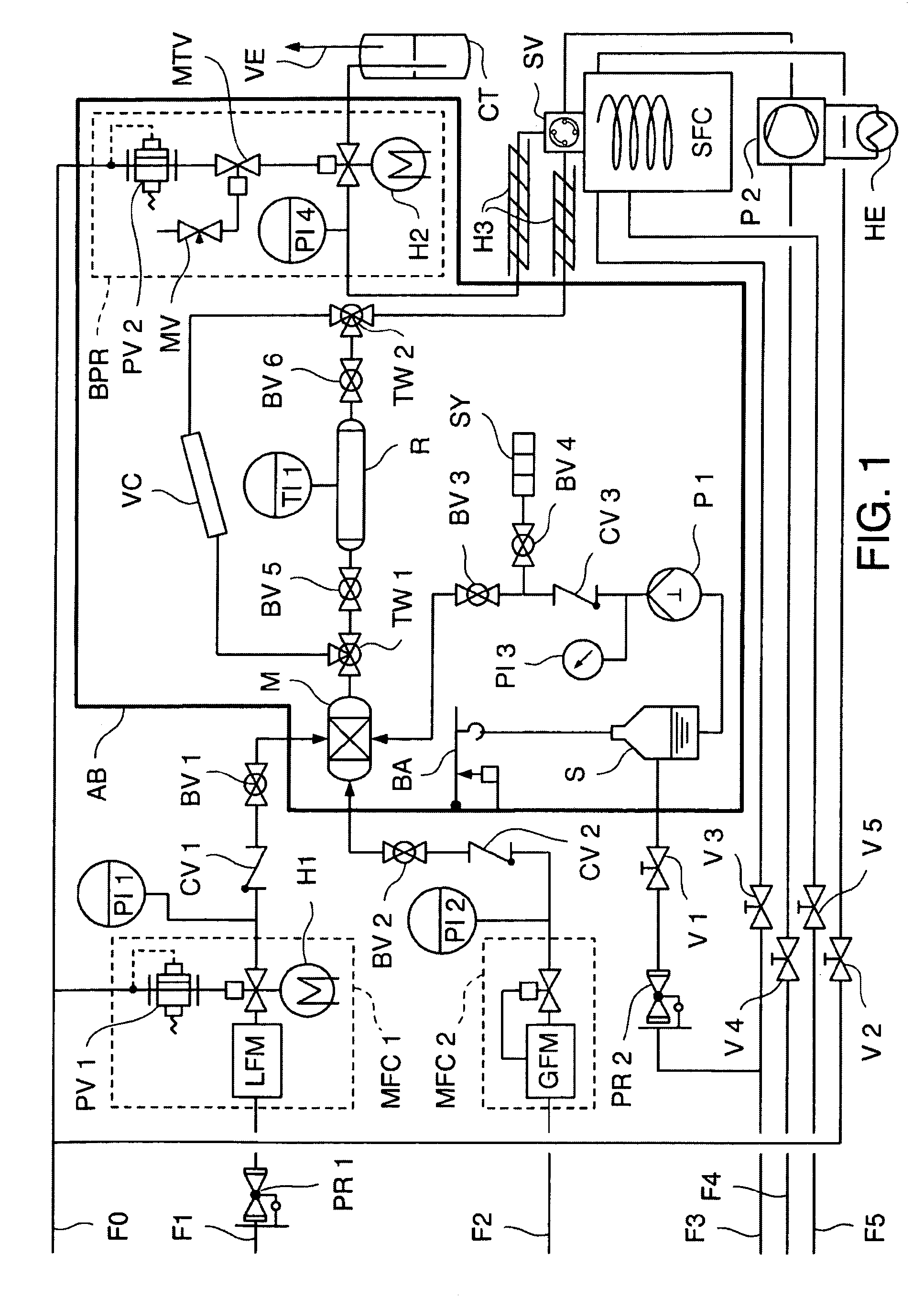
[0062]FIG. 1 shows a flow diagram of an arrangement for carrying out the method pursuant to the invention according to a first embodiment of the invention (Example I), wherein:
[0063]F0=compressed air (6 bar), F1=liquid CO2, F2=H2, F3=N2, F4=liquid CO2 (approx. 40-70 bar), F5=H2, PR=reduction valve, MFC=mass flow controller, LFM=flowmeter, GFM=gas flowmeter, H=heat, PI=pressure indicator, PV=proportional valve, CV=check valve, BV=ball valve, AB=incubator, V=lockable valve, M=mix chamber, S=reservoir for cosolvents or derivatization reagent, BA=scale, P=piston pump, SY=flushing syringe, TW=three-way valve, R=reactor, VC=high pressure visual cell, TI=temperature indicator, BPR=back pressure regulator valve, MTV=magnetic tunneling valve, MV=metering valve, CT=cold trap, VE=ventilation, SV=high pressure switchover valve, HE=heat exchanger, SFC=supercritical fluid chromatograph.
[...
example ii
[0073]The same reaction apparatus as in Example I and shown in FIG. 1 is used in the example described herein, wherein a continuously stirred tank reactor is utilized instead of a flow tube. The catalyst provided herein is homogeneously dissolved in an ionic liquid phase.
1. Production of the Catalyst Solution
[0074]For the exact dosage of the metal complex 24 μmol of [Ru(cod)(methallyl)2] and 84 μmol of PBu4TPPMS (ratio 1:3.5) were dissolved under argon atmosphere in 3 ml of DCM, and of this amount 0.25 ml (2 μmol of [Ru]) were transferred into another Schlenk flask. In addition, 2 equivalents of EMIMCl were added by means of a parent solution in DCM. Then was added 1 ml of the ionic liquid 1-(N,N-dethylaminoethyl)-[sic] 2,3-dimethylimidazolium bis(trifluoromethylsulfonyl)imide ([EAMMIM][BTA]) and the mixture was stirred for 2 h at 70° C. in a high vacuum to remove the DCM.
2. Implementation of the Hydrogenation
[0075]A hydrogenation within a test setup was carried out according to the...
example iii
[0080]The example described herein, like Example II, uses only a heterogeneous polymer-bound amine QuadraPure™-DMA instead of an amino functionalized ionic liquid.
1. Production of the Catalyst Solution
[0081]For the exact dosage of the metal complex an amount of 24 μmol of [Ru(cod)(methallyl)2] and 84 μmol of PBu4TPPMS (ratio 1:3.5) was dissolved in 3 ml of DCM under an argon atmosphere and 0.25 ml (2 μmol of [Ru]) were transferred into another Schlenk flask. As additive were added 2 equivalents of EMIMCl, likewise by means of a parent solution in DCM. Then 1 ml of the ionic liquid ([EAMMIM][BTA]) was added and the mixture was stirred for 2 h at 70° C. in a high vacuum to remove the DCM.
2. Implementation of the Hydrogenation
[0082]A hydrogenation was carried out within a test setup according to the flow diagram of FIG. 1 using the catalyst / stabilizer solution produced in 1. The procedure was carried out as follows:
Filling of the Reactor
[0083]Into the 10 ml stirred tank reactor was add...
PUM
| Property | Measurement | Unit |
|---|---|---|
| pressure | aaaaa | aaaaa |
| concentrations | aaaaa | aaaaa |
| concentrations | aaaaa | aaaaa |
Abstract
Description
Claims
Application Information
 - R&D Engineer
- R&D Manager
- IP Professional
- Industry Leading Data Capabilities
- Powerful AI technology
- Patent DNA Extraction
Browse by: Latest US Patents, China's latest patents, Technical Efficacy Thesaurus, Application Domain, Technology Topic.
© 2024 PatSnap. All rights reserved.Legal|Privacy policy|Modern Slavery Act Transparency Statement|Sitemap