Compact edge illuminated diffractive display

a technology of diffractive display and compact edge, which is applied in the field of compact edge illumination diffractive display, can solve the problems of complex opto-mechanical design problems, optical design limits the miniaturization possible with either approach, and image sizes and resolutions required for typical applications such as internet browsing or viewing high definition films are already beyond the scope of display technologies currently available for use in mobile devices

Active Publication Date: 2015-07-07
DIGILENS
View PDF14 Cites 106 Cited by
  • Summary
  • Abstract
  • Description
  • Claims
  • Application Information

AI Technical Summary

Benefits of technology

[0007]It is an object of the present invention to provide compact solid-state high-resolution data projection display with a thin form factor.

Problems solved by technology

However, image sizes and resolutions required for typical applications such as internet browsing or viewing high definition films are already beyond the scope of display technologies currently available for use in mobile devices.
Optical design limits the miniaturization possible with either approach, even when solid state lasers are used as the light source.
Although MOEMS are much smaller than LCDs or DLPs they present complex opto-mechanical design problems.
Achieving the mechanical robustness required in portable applications is also a challenge.
A further problem is that it is also difficult to correct laser speckle in scanned displays.

Method used


Image

  • Compact edge illuminated diffractive display
  • Compact edge illuminated diffractive display
  • Compact edge illuminated diffractive display

Examples


Embodiment Construction

[0037]It will apparent to those skilled in the art that the present invention may be practiced with some or all of the present invention as disclosed in the following description. For the purposes of explaining the invention well-known features of optical technology known to those skilled in the art of optical design and visual displays have been omitted or simplified in order not to obscure the basic principles of the invention.

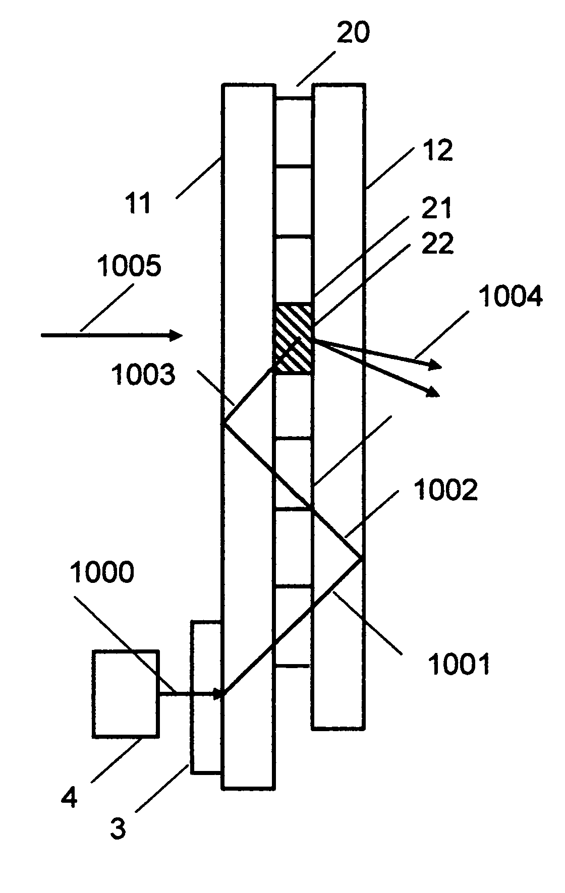
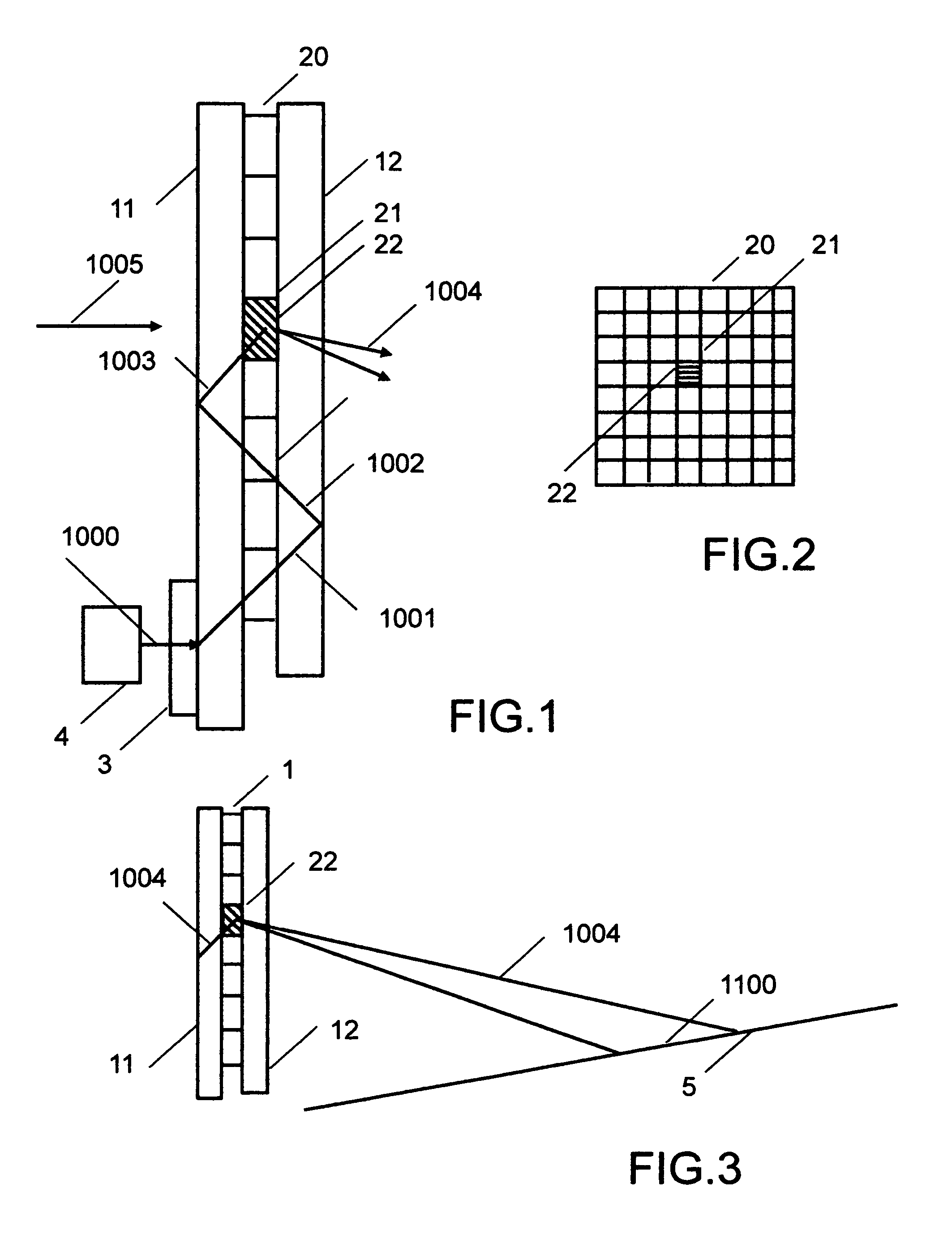
[0038]Unless otherwise stated the term “on-axis” in relation to a ray or a beam direction refers to propagation parallel to an axis normal to the surfaces of the optical components used in the embodiments of the invention. In the following description the terms light, ray, beam and direction may be used interchangeably and in association with each other to indicate the direction of propagation of light energy along rectilinear trajectories.

[0039]Parts of the following description will be presented using terminology commonly employed by those skilled in the a...


PUM

PropertyMeasurementUnit
thicknessaaaaaaaaaa
first wavelengthaaaaaaaaaa
transparentaaaaaaaaaa

Abstract

There is provided a projection display device comprising: a light source, an SBG device comprising a multiplicity of separately SBG elements sandwich between transparent substrate to which transparent electrodes have been applied. The substrates function as a light guide. A least one transparent electrode comprises plurality of independently switchable transparent electrodes elements, each electrode element substantially overlaying a unique SBG element. Each SBG element encodes image information to be projected on an image surface. Light coupled into the light guide, undergoes total internal reflection until diffracted out to the light guide by an activated SBG element. The SBG diffracts light out of the light guide to form an image region on an image surface when subjected to an applied voltage via said transparent electrodes.

Description

REFERENCE TO PRIORITY APPLICATION[0001]This application claims the priority of U.S. Provisional Patent Application No. 61 / 272,601 with filing date 9 Oct. 2009 entitled “Compact edge illuminated diffractive display”.REFERENCE TO EARLIER APPLICATIONS[0002]This application incorporates by reference in their entireties PCT Application No. PCT / US2004 / 014124 by Popovich et al, entitled “Switchable Viewfinder Display”; PCT Application No PCT / IB2008 / 001909 by Popovich et al, entitled “Laser Illumination Device”; PCT Application No PCT US2006 / 043938 by Popovich et al, entitled “Method and Apparatus for Switching a PDLC device” and U.S. Provisional Patent Application No. 61 / 272,601 with filing date 9 Oct. 2009 entitled “Compact edge illuminated diffractive display”.BACKGROUND OF THE INVENTION[0003]This invention relates to a display device, and more particularly to a compact edge-illuminated projection display based on switchable Bragg gratings.[0004]There is growing consumer demand for proje...

Claims


Application Information

Patent Timeline
Patent Type & Authority Patents(United States)
IPC IPC(8): G03B21/00G03H1/10G02B6/02H01L33/10G01J3/18G03F7/20H04N9/31
CPCG02B6/02076H01L33/10G01J3/1895G03F7/70316G03B21/005H04N9/315H04N9/3173G02F1/225
Inventor POPOVICH, MILAN MOMCILOWALDERN, JONATHAN DAVID
Owner DIGILENS
Why Eureka
Try Eureka