
Method, device and system for activating on-line patch

a technology of patch activation and patch mode, applied in computing, instruments, electric digital data processing, etc., can solve the problems of patch activation mode, jump instruction becomes not entirely reliable, and cannot meet the requirements of telecommunications software reliability

Active Publication Date: 2015-07-07
HUAWEI TECH CO LTD
View PDF13 Cites 1 Cited by
  • Summary
  • Abstract
  • Description
  • Claims
  • Application Information

AI Technical Summary

Benefits of technology

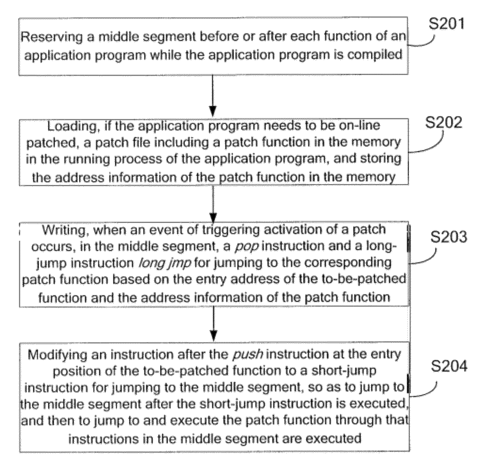
The present invention provides a method and system for activating software patches online to enhance security and reliability. The method involves modifying the jump instruction to the patch function by replacing the entry position of the function with a short-jump instruction, which ensures that only one instruction needs to be modified. This approach avoids the risk of covering other instructions in the critical segment when activating a patch, which could compromise security and reliability under the multi-thread scheduling mechanism. Overall, this method ensures the secure and reliable activation of online patches without interrupting service.

Problems solved by technology

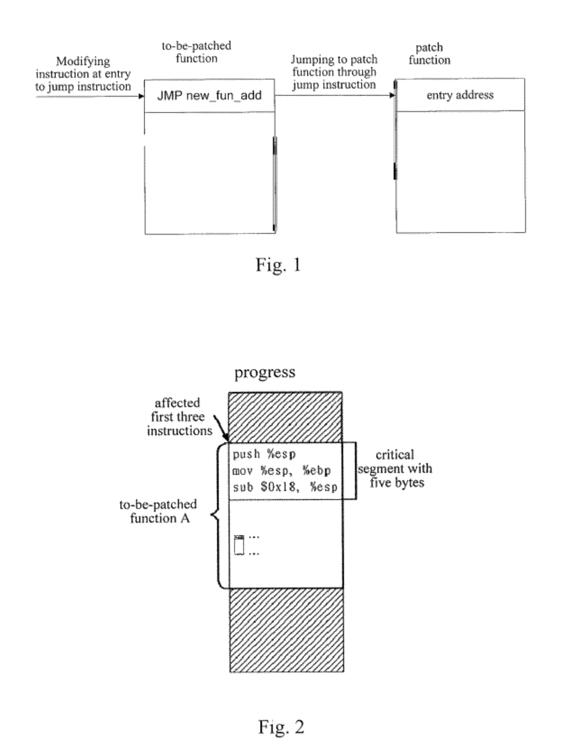
However, due to the characteristics of the instructions of the X86 system and the scheduling mode of the Linux, the patch activating mode for simply modifying the instruction at the entry of a replaced function to a jump instruction becomes not entirely reliable, and cannot satisfy the requirements on the reliability of telecommunications software.
since only the EIP value of the current thread is checked prior to replacing the function, once there is a thread in the signal processing function, and the return address of the signal is in the critical segment, there will be program error when the thread returns after processing the signal processing function, because the critical segment has already been covered by the jump instruction.
Accordingly, the security and reliability in activating patches can still not be guaranteed by such prior art technical solution.

Method used


Image

  • Method, device and system for activating on-line patch
  • Method, device and system for activating on-line patch
  • Method, device and system for activating on-line patch

Examples


Embodiment Construction

[0040]To make more clear the objectives, technical solutions and advantages of the embodiments of the present invention, the technical solutions according to the embodiments of the present invention will be clearly and completely described below with reference to the accompanying drawings. Apparently, the embodiments as described below are merely partial, rather than entire, embodiments of the present invention. On the basis of the embodiments of the present invention, all other embodiments obtained by the persons skilled in the art without paying any creative effort shall all fall within the protection scope of the present invention.

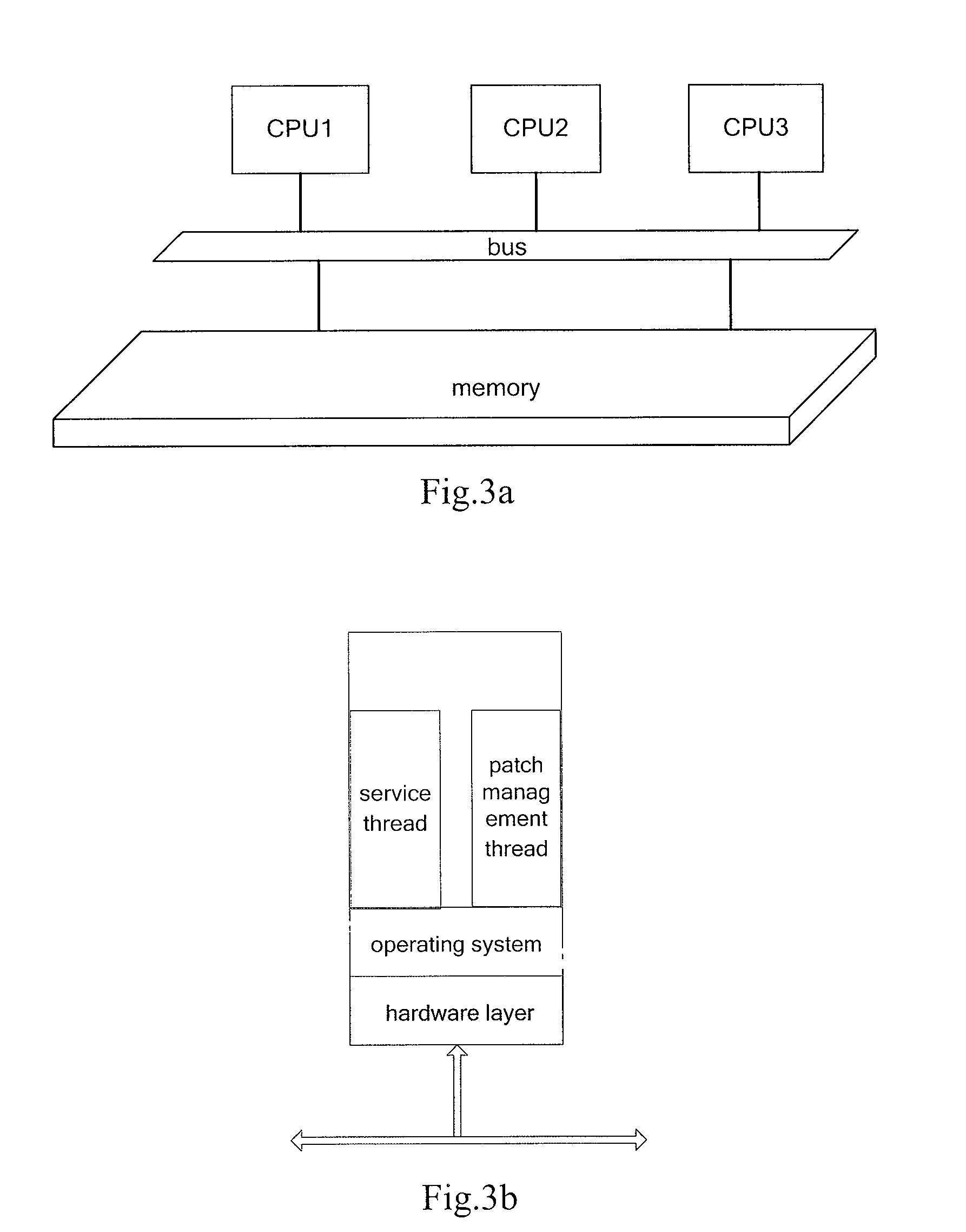
[0041]Referring to FIGS. 3a and 3b, which are schematic diagrams illustrating the structure of the communication system according to the embodiments of the present invention, the communication system according to the embodiments of the present invention supports activation of software on-line patches under the multi-thread environment. As should be expl...


PUM


Abstract

Embodiments of the present invention provide a method, a device and a system for activating an on-line patch. The method comprises: positioning an address of a patch function and an entry address of a to-be-patched function; writing, in a middle segment, a long-jump instruction for jumping to the patch function based on the address of the patch function and the entry address of the to-be-patched function, where the middle segment is a storage space, which is located before or after the entry position of the to-be-patched function and can at least store one long-jump instruction; and modifying an instruction at the entry position of the to-be-patched function to a short-jump instruction for jumping to the middle segment, so as to jump to the middle segment after the short jump instruction is executed, and then to jump to and execute the patch function through that instructions in the middle segment are executed.

Description

CROSS-REFERENCE TO RELATED APPLICATIONS[0001]This application is a continuation of International Application No. PCT / CN2010 / 078271, filed Oct. 30, 2010, which claims priority to Chinese Patent Application No. 201010113646.2, filed Feb. 11, 2011, both of which are hereby incorporated by reference in their entireties.FIELD OF THE INVENTION[0002]The present invention relates to the technical field of computers, and more particularly, to a method, a device and a system for activating on-line patches.BACKGROUND OF THE RELATED ART[0003]Widely used in various types of software, on-line patches are patches that become effective during running of programs without restarting the programs. Referring to FIG. 1, the basic principle for activating an on-line patch is to replace the instruction at the entry of an original function (namely a to-be-patched function) with a jump instruction, and then to jump the program that invokes the original function to a patch function for execution through the ...

Claims


Application Information

Patent Timeline
Patent Type & Authority Patents(United States)
IPC IPC(8): G06F9/445
CPCG06F8/67G06F8/656
Inventor YU, JIAQIANGZHENG, WEI
Owner HUAWEI TECH CO LTD
Learn More