Eureka AIR delivers breakthrough ideas for toughest innovation challenges, trusted by R&D personnel around the world.

Coding apparatus and method for encoding image data

a coding apparatus and image data technology, applied in the field of image coding apparatus and image coding method, can solve the problem of increasing the delay until the feedback of a generated code amount is reflected in the quantization coefficient, and achieve the effects of reducing the delay of feedback of a generated code amount, controlling a quantization coefficient, and high accuracy

Inactive Publication Date: 2015-07-07
CANON KK
View PDF4 Cites 0 Cited by
  • Summary
  • Abstract
  • Description
  • Claims
  • Application Information

AI Technical Summary

Benefits of technology

[0011]The present invention has been made to solve the above problems, and enables reducing a delay of feedback of a generated code amount and controlling a quantization coefficient at high accuracy even when the size of a coding block is changeable in an image frame.

Problems solved by technology

However, when the size of a coding block is changeable, if the quantization coefficient is determined by feeding back the generated code amount of a coding block similarly to the conventional coding method, the delay until feedback of a code amount is reflected in the quantization coefficient may increase.

Method used


Image

  • Coding apparatus and method for encoding image data
  • Coding apparatus and method for encoding image data
  • Coding apparatus and method for encoding image data

Examples


first embodiment

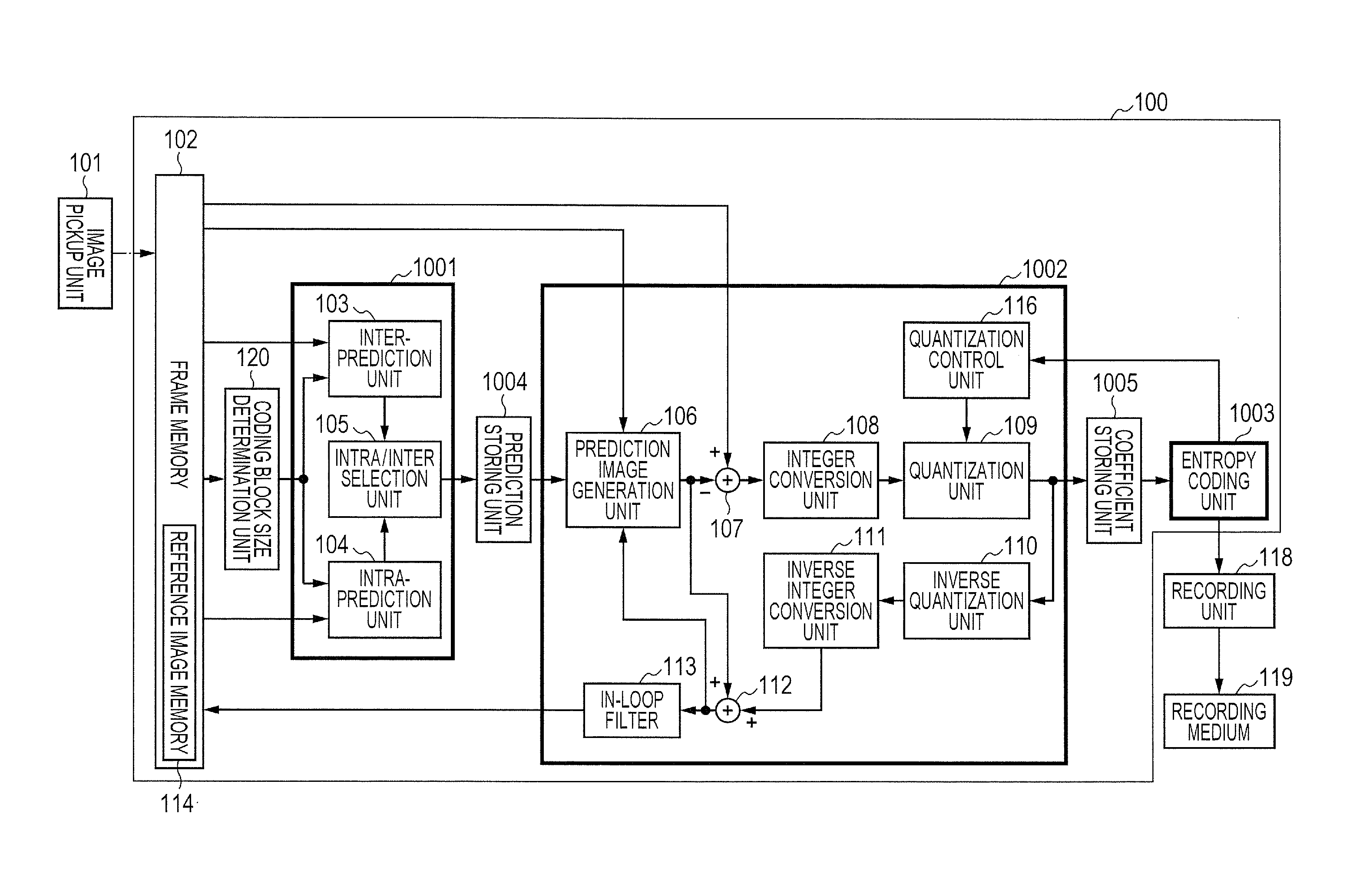
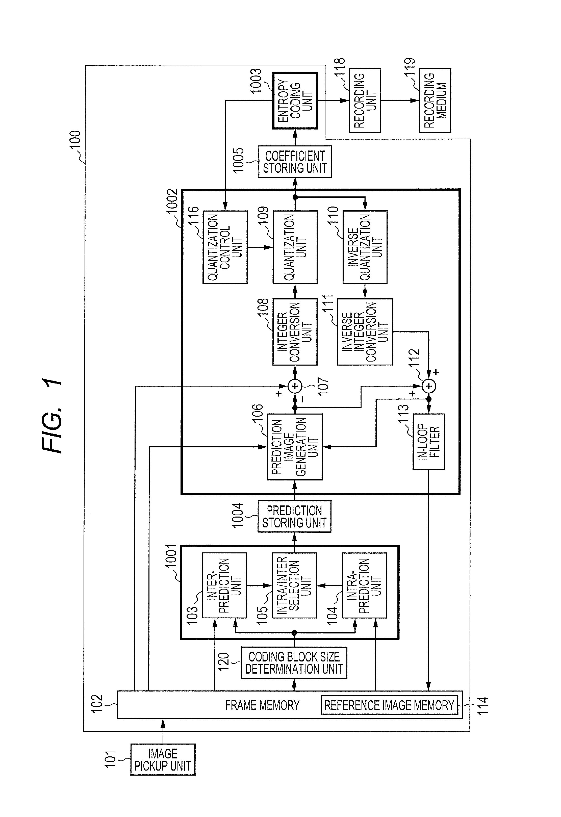
[0020]FIG. 1 is a block diagram exemplifying the arrangement of an image pickup apparatus including an image coding apparatus 100 according to the first embodiment of the present invention. In the image pickup apparatus of FIG. 1, building components not particularly relevant to the image coding apparatus of the present invention are omitted or simplified.

[0021]In FIG. 1, the image pickup apparatus includes the image coding apparatus 100 according to the present invention, an image pickup unit 101 which includes a camera unit including a lens and image pickup sensor to acquire image data, and a recording unit 118. The image pickup apparatus is configured to detachably mount a recording medium 119.

[0022]The image coding apparatus 100 includes a frame memory 102, a coding block size determination unit 120 which determines the size (number of pixels) of a coding block serving as a coding unit (CU), a prediction method determination unit 1001, a prediction storing unit 1004 which tempor...

second embodiment

[0047]The second embodiment of the present invention will be described with reference to FIG. 3.

[0048]FIG. 3 is a block diagram exemplifying the arrangement of an image pickup apparatus including an image coding apparatus 300 according to the second embodiment. The image pickup apparatus of FIG. 3 is different from that of FIG. 1 in a prediction method determination unit 3001, and further includes an integer conversion size determination unit 301 which determines a TU size. The remaining arrangement is the same as that in the image pickup apparatus according to the first embodiment, and a description thereof will not be repeated.

[0049]After an intra / inter selection unit 105 selects a prediction method, it notifies the integer conversion size determination unit 301 of a prediction method selection signal.

[0050]When the size of a coding subject CU is 32×32 or 16×16, the integer conversion size determination unit 301 sets the TU size to be smaller than the CU size.

[0051]In a case where...


PUM


Abstract

When performing pipeline processes by a prediction method determination unit, prediction coding unit, and entropy coding unit, the size of a block of an integer conversion unit (transform unit: TU) is set smaller than the size of a CU (Coding Unit). A generated code amount is fed back to the prediction coding unit on the TU basis, reducing a feedback delay and increasing the quantization control accuracy.

Description

BACKGROUND OF THE INVENTION[0001]1. Field of the Invention[0002]The present invention relates to an image coding apparatus and image coding method and, more particularly, to a technique suitable for use in a coding apparatus arranged to change a size of a block as a coding unit.[0003]2. Description of the Related Art[0004]Recently, as digitization of information associated with so-called multimedia including audio signal and image signal has made rapid progress, compression coding / decoding techniques for the image signal are receiving attention. The compression coding / decoding techniques can reduce the storage capacity necessary to store image signals and the band necessary for transmission, and thus are very important techniques in the multimedia industry.[0005]These compression coding / decoding techniques compress the information amount / data amount by using the degree of autocorrelation (that is, redundancy) which many image signals have therein. The redundancy of an image signal i...

Claims


Application Information

Patent Timeline
Patent Type & Authority Patents(United States)
IPC IPC(8): G06K9/36G06T9/00
CPCG06T9/00H04N19/176H04N19/61H04N19/124H04N19/146
Inventor ENDO, HIROAKI
Owner CANON KK
Why Eureka
Eureka Blog
Learn More