Power module package

a power module and package technology, applied in the field of power module packages, can solve the problems of inability to easily access, high cost, and limited underground resources, and achieve the effect of simplifying the process and reducing costs

Inactive Publication Date: 2015-07-07
SAMSUNG ELECTRO MECHANICS CO LTD
View PDF10 Cites 4 Cited by
  • Summary
  • Abstract
  • Description
  • Claims
  • Application Information

AI Technical Summary

Benefits of technology

[0012]The present invention has been made in an effort to provide a power module package that can be implemented at low cost by being manufactured using an automation process and simplifying a process.
[0013]Further, the present invention has been made in an effort to provide a power module package that has improved heat radiating characteristics and can be used at high temperature by minimizing an effect of heat generation of a power unit on a control unit.
[0014]In addition, the present invention has been made in an effort to provide a power module package having a structure in which a minimum creepage and clearance between a lead frame and a heat radiating plate of the module is easily secured.

Problems solved by technology

Underground resources are limited but energy usage has been increased every year.
The industrial and high-capacity power modules with a case according to the related art cannot be mass-produced, are expensive, and cannot be easily accessed.

Method used


Image

  • Power module package
  • Power module package
  • Power module package

Examples


first preferred embodiment

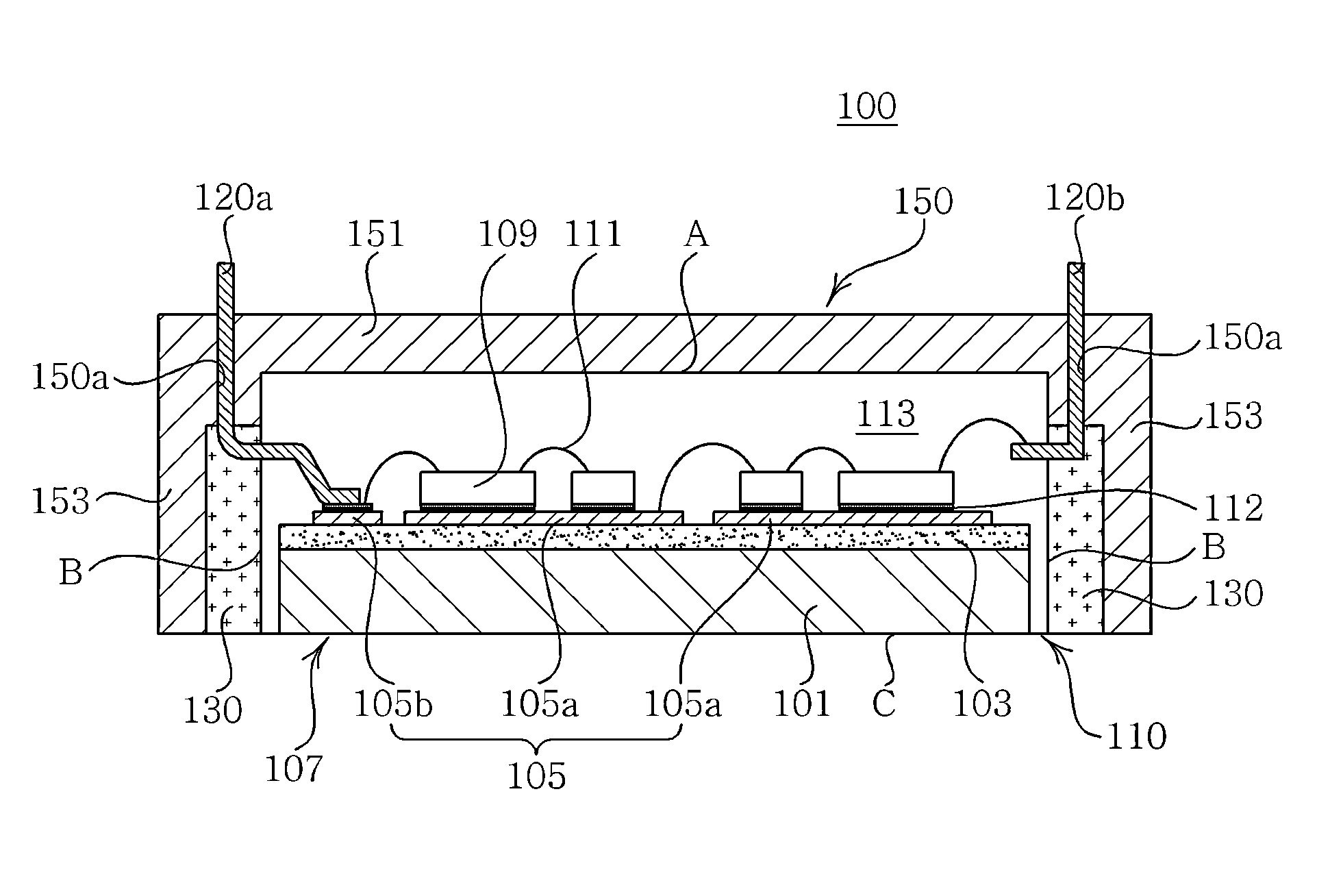
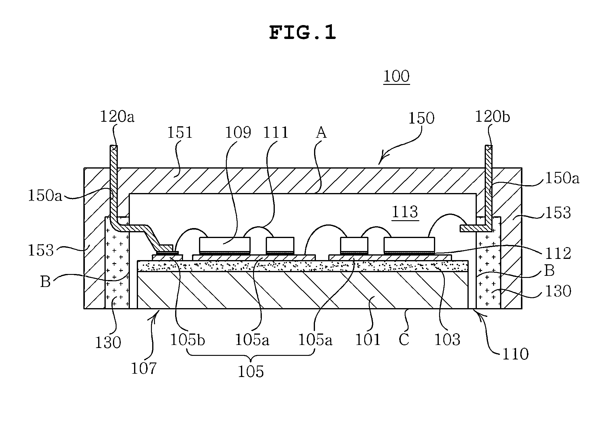
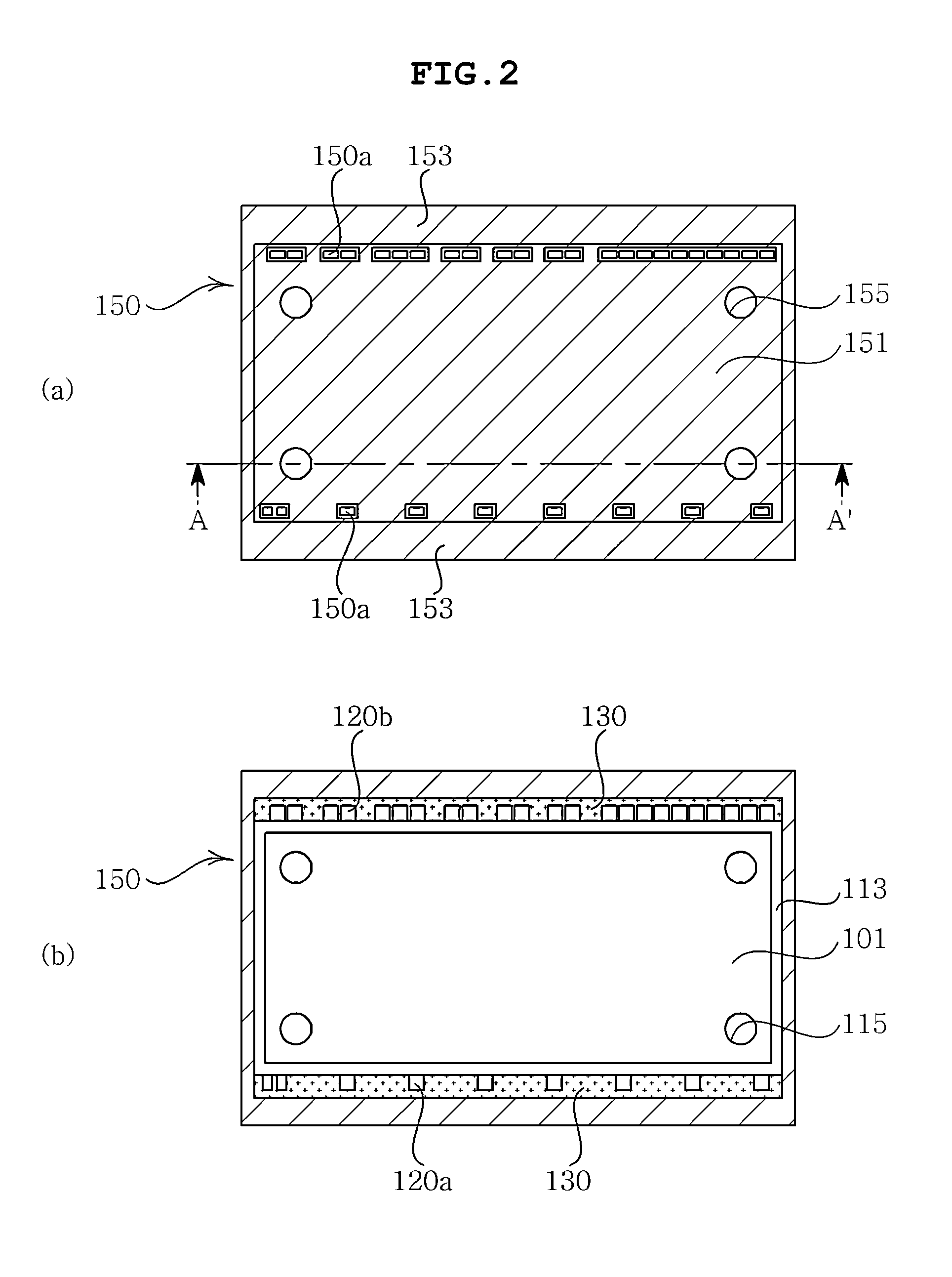
[0046]FIG. 1 is a cross-sectional view showing a structure of a power module package according to a first preferred embodiment of the present invention, FIG. 2 is a plan view showing a top surface and a bottom surface of the power module package of FIG. 1, FIGS. 3 and 4 each are a cross-sectional view of the line A-A′ of FIG. 2 and cross-sectional views showing a structure with which a first fastening member is fastened, FIGS. 5 and 6 each are a cross-sectional view showing a structure of a fastening groove formed in the power module package of FIG. 1 and a cross-sectional view showing a structure in which a second fastening member is fastened with the fastening groove, and FIGS. 7 and 8 are cross-sectional views of a structure in which a third fastening member protruded from an inner wall of a case of the power module package of FIG. 1 is fastened with the first module.

[0047]Referring to FIG. 1, a power module package 100 according to the preferred embodiment of the present inventi...

second preferred embodiment

[0106]FIG. 9 is a cross-sectional view showing a structure of a power module package according to a second preferred embodiment of the present invention.

[0107]The description of overlapping components with the foregoing first preferred embodiment of the present invention will be omitted in the second preferred embodiment of the present invention. Further, the overlapping components with the first preferred embodiment of the present invention are denoted by the same reference numerals.

[0108]Referring to FIG. 9, a power module package 200 according to the preferred embodiment of the present invention may include the first module 110, the second module 180 disposed on the first module 110, and the case 150 enclosing the first module 110 and the second module.

[0109]Further, the power module package may further include a bonding member (not shown) formed between the first module 110 and the second module 180.

[0110]The first module 110 according to the preferred embodiment of the present ...

third preferred embodiment

[0124]FIG. 10 is a cross-sectional view showing a structure of a power module package according to a third preferred embodiment of the present invention.

[0125]The description of overlapping components with the foregoing second preferred embodiment of the present invention will be omitted in the third preferred embodiment of the present invention. Further, the overlapping components with the second preferred embodiment of the present invention are denoted by the same reference numerals.

[0126]Referring to FIG. 10, a power module package 300 according to the preferred embodiment of the present invention may include the first module 110, the second module 180 disposed on the first module 110, and the case 150 enclosing the first module 110 and the second module 180.

[0127]Further, the power module package 300 may further include a bonding member (not shown) formed between the first module 110 and the second module 180.

[0128]The first module 110 according to the preferred embodiment of th...


PUM


Abstract

Disclosed herein is a power module package including: a first module configured of a first substrate having one surface and the other surface, a first semiconductor chip mounted on one surface of the first substrate, and a first sealing member formed to cover the first semiconductor chip mounted on one surface of the first substrate from both sides in a thickness direction of the first substrate and expose the other surface of the first substrate; and a case enclosing the first module.

Description

CROSS REFERENCE TO RELATED APPLICATION[0001]This application claims the benefit of Korean Patent Application No. 10-2012-0146346, filed on Dec. 14, 2012, entitled “Power Module Package”, which is hereby incorporated by reference in its entirety into this application.BACKGROUND OF THE INVENTION[0002]1. Technical Field[0003]The present invention relates to a power module package.[0004]2. Description of the Related Art[0005]Underground resources are limited but energy usage has been increased every year. Therefore, all the countries are directing more attention and effort to the development of alternative energy.[0006]This effort has continued to the development of technologies of implementing high efficiency with less energy. One of the technologies is the very power module.[0007]The power module may be largely classified into an inverter, a converter, and a device for a motor. There are various types of power modules according to the purpose and the usage thereof has been continuousl...

Claims


Application Information

Patent Timeline
Patent Type & Authority Patents(United States)
IPC IPC(8): H01L23/12H01L23/34H01L23/053H01L23/373
CPCH01L23/053H01L2224/32225H01L2224/48137H01L2224/48227H01L2224/48247H01L2224/73265H01L2924/19107H01L23/3735H01L2924/13034H01L2924/13055H01L2924/1305H01L2924/13091H01L2924/00012H01L2924/00H01L2924/00014H01L24/73H01L2224/48091H01L23/28H01L25/065
Inventor KIM, TAE HYUNKIM, KWANG SOOYUN, SUN WOOLEE, YOUNG KIYOO, DO JAE
Owner SAMSUNG ELECTRO MECHANICS CO LTD
Why Eureka
Try Eureka