
Automatic screw tightening apparatus

a screw tightening and automatic technology, applied in the direction of screwdrivers, metal-working apparatus, wrenches, etc., can solve the problems of large screw feeding mechanism, disadvantageous space of screw tightening apparatus, screw tip of screw stuck in the hose, etc., and achieve the effect of reducing the range of the screw tightening mechanism

Active Publication Date: 2015-07-14
OHTAKE ROOT IND
View PDF5 Cites 6 Cited by
  • Summary
  • Abstract
  • Description
  • Claims
  • Application Information

AI Technical Summary

Benefits of technology

The present invention provides an automatic screw tightening apparatus that solves problems of damaged screws and difficulty in assembly. It is small-sized, compact, and has a relaxed moving range. The screw tightening mechanism uses air suction to transfer screws smoothly without getting stuck, which leads to improved reliability. The apparatus allows quick and automatic tightening of screws against a subject. It is easy to engage with different kinds of screws and maintains a simple configuration and low fabrication cost. The apparatus provides a plurality of feed head parts corresponding to different kinds of screws, allowing quick and easy engagement with various screws. This simplifies the configuration and makes maintenance easy.

Problems solved by technology

For example, tips of screws often get stuck in the hose.
Further, since the screw feeding mechanism should move with the feeder hose attached to the screw tightening head, the screw feeding mechanism is large.
Furthermore, since the moving range of the screw tightening mechanism should be wide, the screw tightening apparatus is disadvantageous in space.
Moreover, unexpected accidents may happen due to contact of workers or subjects with the hose or others.

Method used


Image

  • Automatic screw tightening apparatus
  • Automatic screw tightening apparatus
  • Automatic screw tightening apparatus

Examples


Embodiment Construction

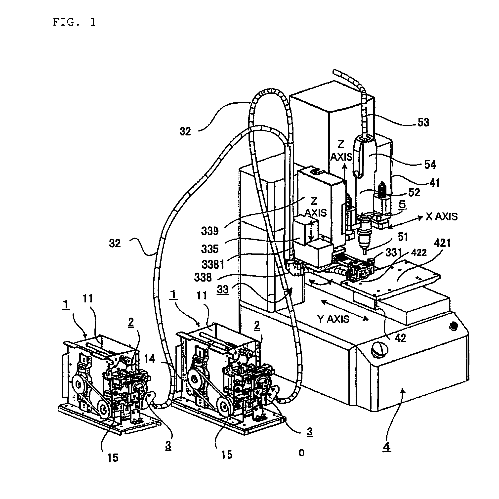
[0036]An embodiment of the present invention transfers screws one by one from a screw feeding mechanism to a screw tightening mechanism (driver) through a transfer tube such as a vinyl tube or hose with the head portions of the screws being in the lead in the transfer tube, and engages the head portion of each of the transferred screws with a fore end of a driver bit portion of the screw tightening mechanism by air suction of the screw tightening mechanism, thereby automatically and consecutively tightening the screws against desired screwed portions.

[0037]Hereinafter, an automatic screw tightening apparatus according to an embodiment of the present invention will be described in detail with reference to the accompanying drawings.

[0038][Whole Configuration]

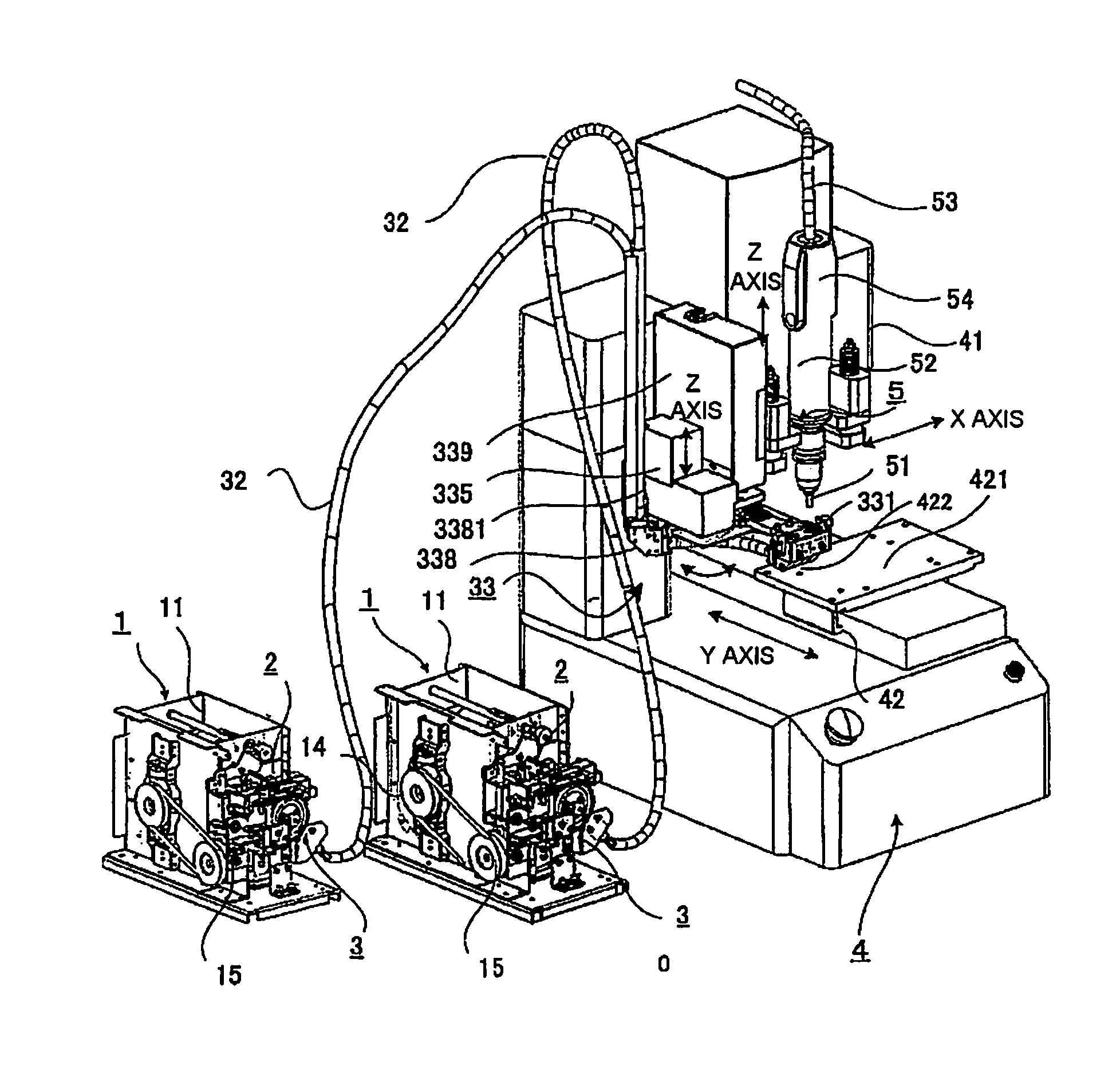
[0039]An automatic screw tightening apparatus according to an embodiment of the present invention with a screw feeding mechanism will be wholly and schematically described with reference to FIG. 1.

[0040]This embodiment is a kind o...


PUM


Abstract

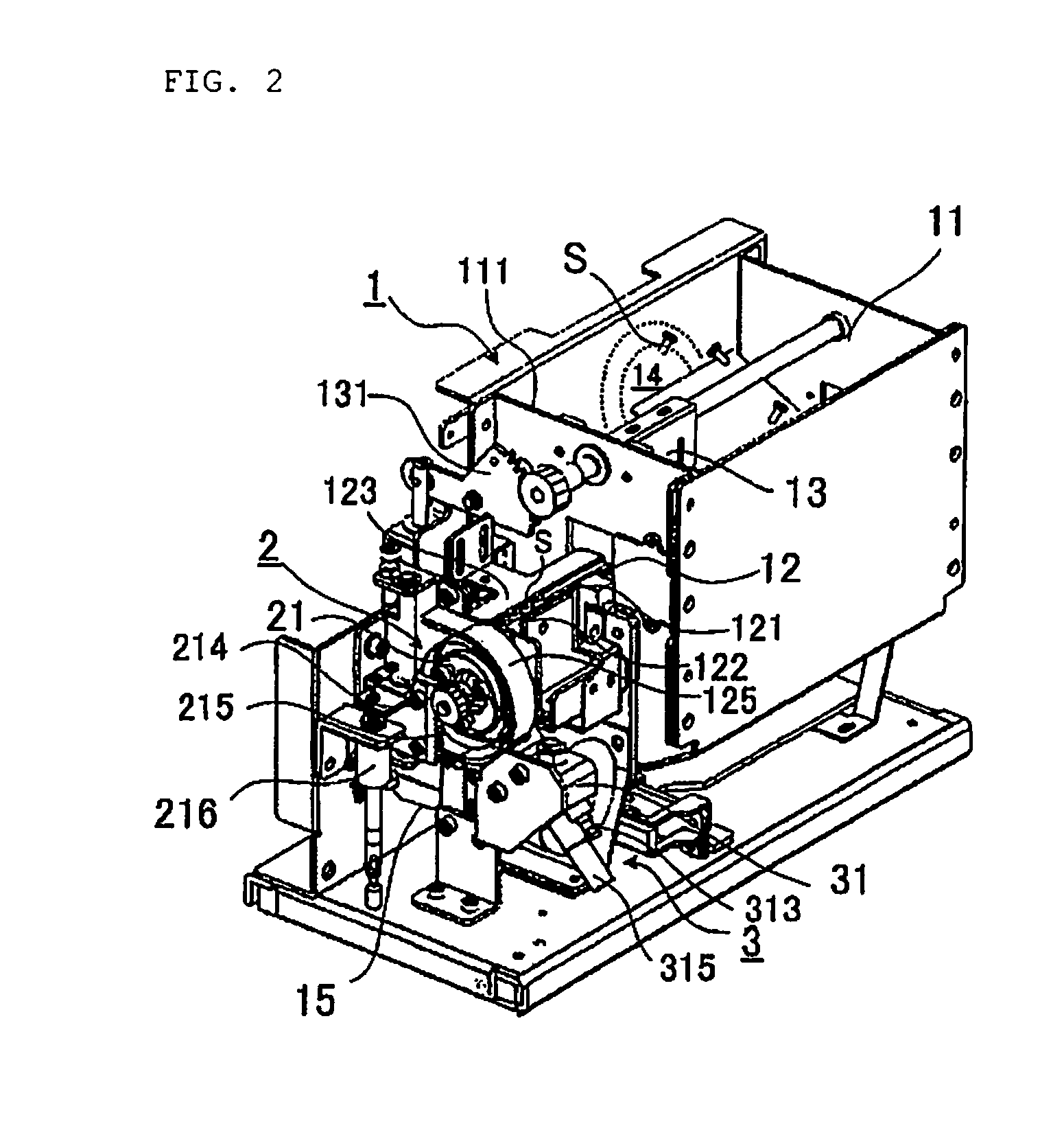
An automatic screw tightening apparatus suppresses damage of an inner wall of a transfer tube, stabilizes the posture of the screw, stably supplies the screw to a driver bit, and reduces screw tightening time. A rotatable arm is installed at the screw discharging unit and a feed head unit is installed at a fore end of the rotatable arm to be brought into close contact with a driver bit portion of a fore end of the screw tightening mechanism. The feed head unit is movable between close contact with the driver bit portion and an evacuation position where the feed head unit is far from the driver bit unit. At the close contact position, the driver bit portion of the fore end of the screw tightening mechanism is brought into contact with the screw and sucks a head portion of the screw to engage the screw.

Description

BACKGROUND OF THE INVENTION[0001]1. Technical Field[0002]The present invention relates to an automatic screw tightening apparatus which automatically tightens a screw against a predetermined screwed portion of a subject by a screw tightening mechanism.[0003]2. Related Art[0004]In an automatic screw tightening apparatus according to the related art for automatically tightening a screw against a predetermined screwed portion of a subject by a screw tightening mechanism as disclosed in Japanese Patent Application Laid-Open No. Hei8-229752, predetermined screws are automatically fed from a screw feeding mechanism to a screw tightening head of a fore end of the screw tightening mechanism one by one. Then, the subject is fixed to a movable table and the screwed position of the subject moves to a predetermined position while the screw tightening head of the screw tightening mechanism moves. Next, the screw is tightened to assemble the subject.[0005]In this case, screws are fed to the screw...

Claims


Application Information

Patent Timeline
Patent Type & Authority Patents(United States)
IPC IPC(8): B25B23/04B23P19/00B23P19/06
CPCB23P19/005B23P19/006B23P19/06B23P19/12B25B23/04
Inventor OTA, YOSHITAKETAKAHASHI, HIROSHI
Owner OHTAKE ROOT IND
Learn More