Construction machine

a construction machine and construction technology, applied in the direction of electrical control, positive displacement liquid engine, exhaust treatment electric control, etc., can solve the problems of reducing the life and reliability of the exhaust gas purifying device, and reducing the regeneration process of the particulate matter removing filter, so as to reduce the rotational load of the engine

Active Publication Date: 2015-07-14
NIHON KENKI CO LTD
View PDF19 Cites 4 Cited by
  • Summary
  • Abstract
  • Description
  • Claims
  • Application Information

AI Technical Summary

Benefits of technology

[0008]However, in the above-mentioned conventional art of Patent Document 1, the delivery displacement of the variable displacement type hydraulic pump, which serves as a hydraulic source, is variably controlled by load sensing. Therefore, during a non-operation time (hereinafter referred to as “unload time”) when all hydraulic actuators are stationary, the delivery displacement of the hydraulic pump is controlled to a flow rate close to a minimum, reducing the rotational load of the engine. In a case where the rotational load of the engine is small as described above, the temperature of the exhaust gas may drop below a temperature required for the filter regeneration of the particulate matter removing filter.

Problems solved by technology

Therefore, in the construction machines adapted to perform load sensing control, when the rotational load of the engine becomes small during the unload time of the hydraulic actuators, it becomes difficult to properly perform the filter regeneration process of the particulate matter removing filter.
Consequently, there is a problem that the lifetime and reliability of the exhaust gas purifying device are decreased.

Method used


Image

  • Construction machine
  • Construction machine
  • Construction machine

Examples


first embodiment

[0035]Herein, FIGS. 1 to 8 show a hydraulic excavator equipped with an exhaust gas purifying device according to the present invention.

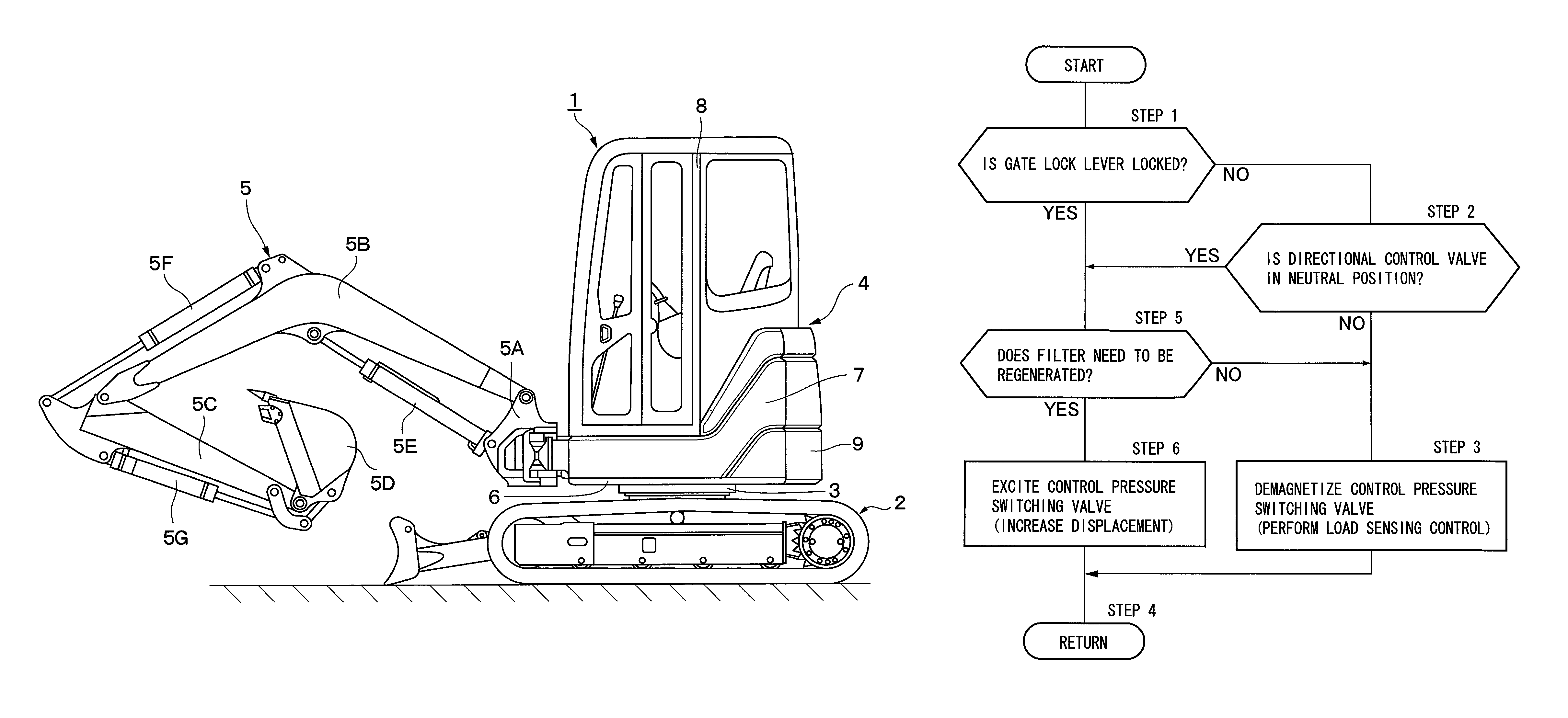
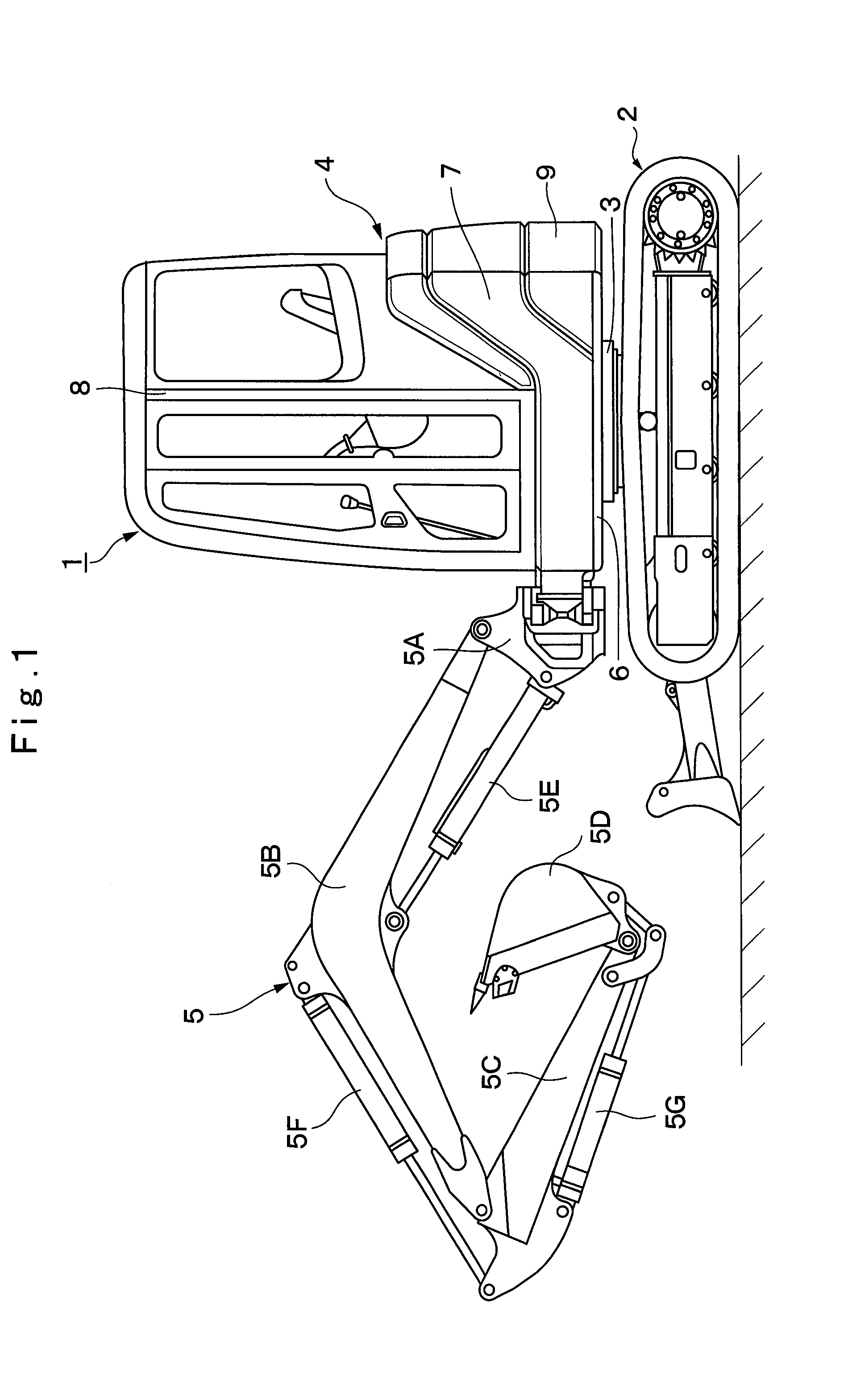
[0036]In the drawings, designated at 1 is a small-sized hydraulic excavator to be used for excavating operation of earth and sand. The hydraulic excavator 1 is generally composed of an automotive crawler type lower traveling structure 2, an upper revolving structure 4 rotatably mounted on the lower traveling structure 2 through a revolving device 3 to constitute the vehicle body together with the lower traveling structure 2, and a working mechanism 5 liftably provided at the front side of the upper revolving structure 4.

[0037]In this case, the working mechanism 5 is constituted as a swing post type working mechanism having a swing post 5A, a boom 5B, an arm 5C, a bucket 5D that serves as a working tool, a swing cylinder (not shown), a boom cylinder 5E, an arm cylinder 5F and a bucket cylinder 5G, for example. In addition, the upper revolving structur...

third embodiment

[0171]However, in the third embodiment, when the control pressure switching valve 57 is switched to the load sensing control release position (k), the rod 101A of the regulation cylinder 101 is extended to bring the stopper 102 into contact with the displacement variable portion 13A. Therefore, the tilting position of the displacement variable portion 13A can be limited within a prescribed range to prevent the tilting angle from exceeding the limit. At this time, the engine 10 can raise the temperature of the exhaust gas to the minimum temperature required for performing the regeneration process of the particulate matter removing filter 19 by rotating the hydraulic pump 13 at the point 103 shown in FIG. 8, thereby preventing the temperature of the exhaust gas from increasing more than necessary.

[0172]Therefore, according to the third embodiment, the regulation cylinder 101 is added to the hydraulic pump 13 as a tilting position limiting device. This prevents the delivery displacemen...


PUM


Abstract

A control pressure switching valve is disposed between a displacement regulator and a pressure control valve. The control pressure switching valve is switched between a control position (j), in which a load sensing control pressure (PLS) is permitted to be outputted from the pressure control valve to the displacement regulator, and a control release position (k), in which the load sensing control pressure (PLS) to be outputted to the displacement regulator is reduced to a prescribed low pressure value. When the regeneration of a filter is determined to be necessary, the controller switches the control pressure switching valve to the control release position (k). When the load sensing control pressure (PLS) is reduced to the low pressure value with the control pressure switching valve switched to the control release position (k), the displacement regulator increases a delivery displacement of a hydraulic pump, thereby increasing rotational load of an engine.

Description

TECHNICAL FIELD[0001]The present invention relates to a construction machine represented by, for example, a hydraulic excavator, a hydraulic crane and a wheel loader, more particularly, relates to a construction machine adapted to perform load sensing control.BACKGROUND ART[0002]As a construction machine represented by a hydraulic excavator, there has been known the one in which the delivery displacement of a variable displacement type hydraulic pump, which serves as a hydraulic source, can be variably controlled so that load pressures of a plurality of hydraulic actuators (namely, various hydraulic cylinders of a working mechanism and hydraulic motors for revolving or traveling) can be load sensed and the pressurized oil can be supplied to the hydraulic actuators in a flow rate corresponding to the load pressures (Patent Document 1).[0003]In addition, as an engine serving as a prime mover of the construction machine, a diesel engine is generally used. In an exhaust gas discharged f...

Claims


Application Information

Patent Timeline
Patent Type & Authority Patents(United States)
IPC IPC(8): F01N3/00E02F9/22F04B49/06F04B49/20F01N11/00F02D41/02E02F9/20E02F3/32F02D29/04F01N3/023
CPCE02F9/2235E02F3/325E02F9/2095E02F9/2217E02F9/2225E02F9/2246E02F9/2285F01N3/023F01N11/002F02D29/04F02D41/029F04B49/06F04B49/20F02D2041/026E02F9/2228E02F9/2296F01N9/002F01N2560/08F01N2560/14F01N2900/08F01N2900/1404F04B1/26Y02T10/40
Inventor YOSHIDA, HAJIMEISHII, HAJIMETAKEBAYASHI, YOSHIFUMINOGUCHI, SHUUHEIKURIKUMA, HAJIME
Owner NIHON KENKI CO LTD
Why Eureka
Try Eureka