Conflicting sub-process identification method, apparatus and computer program

a subprocess and identification method technology, applied in the field of conflicting subprocess identification methods, apparatus and computer programs, can solve the problems of no method of identifying a combination of conflicting subprocesses, poor actual performance, and inability to meet the actual performance of the server, so as to reduce the cost of system building and reduce the amount of human resources and working hours.

Inactive Publication Date: 2015-07-14
NEC CORP
View PDF7 Cites 0 Cited by
  • Summary
  • Abstract
  • Description
  • Claims
  • Application Information

AI Technical Summary

Benefits of technology

[0017]The Exemplary embodiment of the present invention provides a technique for identifying a conflicting combination of sub-processes among a plurality of transaction processing programs in the following manner. Firstly, a comparison is made between processing time periods for which transactions executed in parallel have conflicting parts and for which transactions executed in parallel do not have conflicting parts. This comparison is made for a plurality of transaction processing programs each comprising a plurality of sub-processes. Then, on the basis of correspondence relationships between performance indices obtained from the comparison result, sub-processes competing for a resource are identified. By use of this technique, conflicting combination of sub-processes can be identified easily. Consequently, a reduction in a human resource and working hours can be achieved. Moreover, system building costs can also be reduced.

Problems solved by technology

On the other hand, when the conditions (1) and (2) are not satisfied, a result obtained by using any of the performance models does not reflect the actual performance of the server.
In other words, the actual performance is poorer than the result obtained on the basis of the performance evaluation model.
However, there has been no method of identifying a combination of conflicting sub-processes, heretofore.
Such a above technique has problems that a considerable amount of human resource is required, and that time spent on the identification process is likely to be long.
Moreover, estimation results are not always correct, and estimated conflicting sub-processes are sometimes inaccurate.
As a result, countermeasures taken afterwards come to nothing.
Accordingly, the process of identifying a bottleneck in which sub-processes compete for a resource has been a factor of an increase in system building costs.

Method used


Image

  • Conflicting sub-process identification method, apparatus and computer program
  • Conflicting sub-process identification method, apparatus and computer program
  • Conflicting sub-process identification method, apparatus and computer program

Examples


Embodiment Construction

[0042]A conflicting sub-process identification method of the present invention is described in detail below with reference to the accompanying drawings.

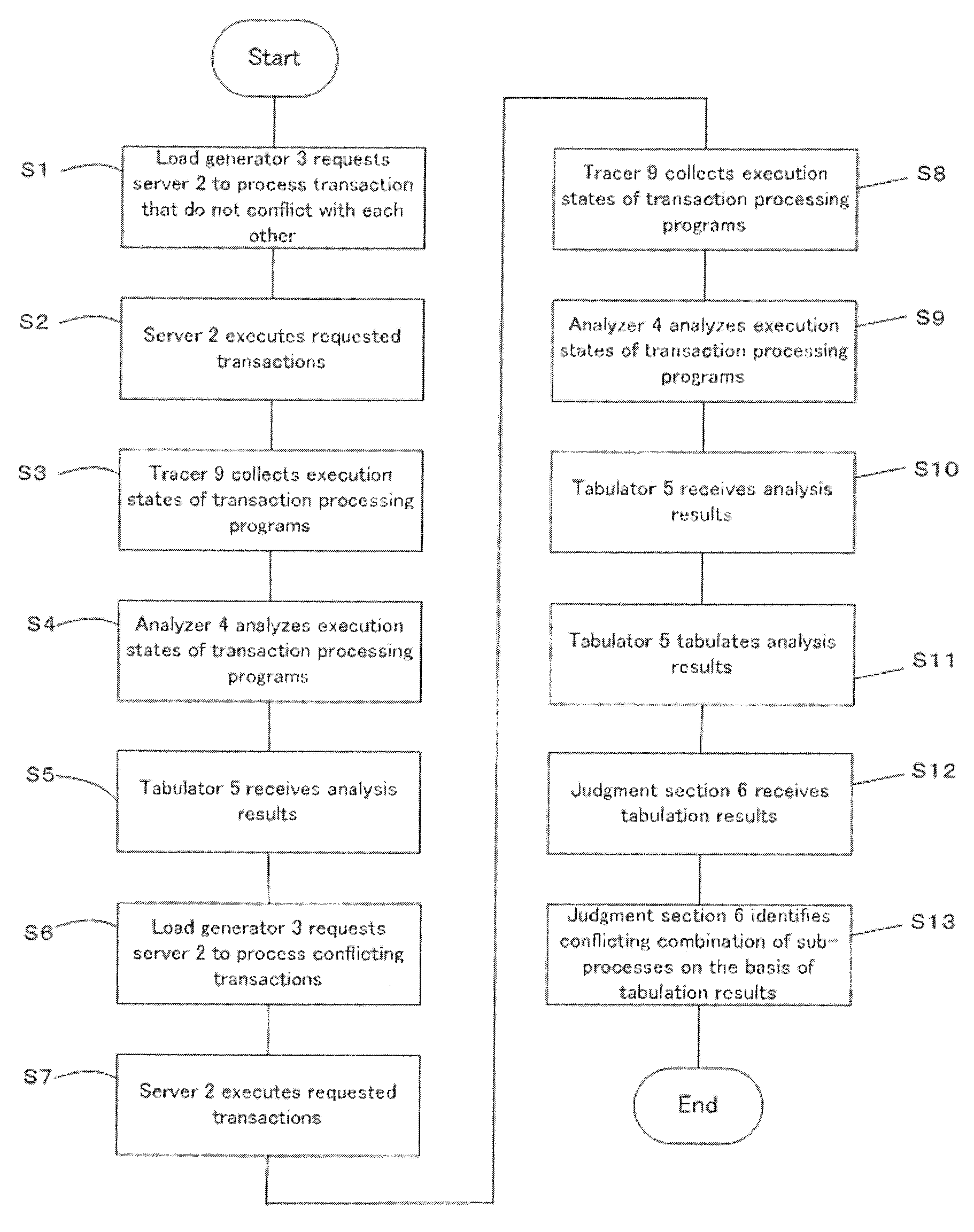
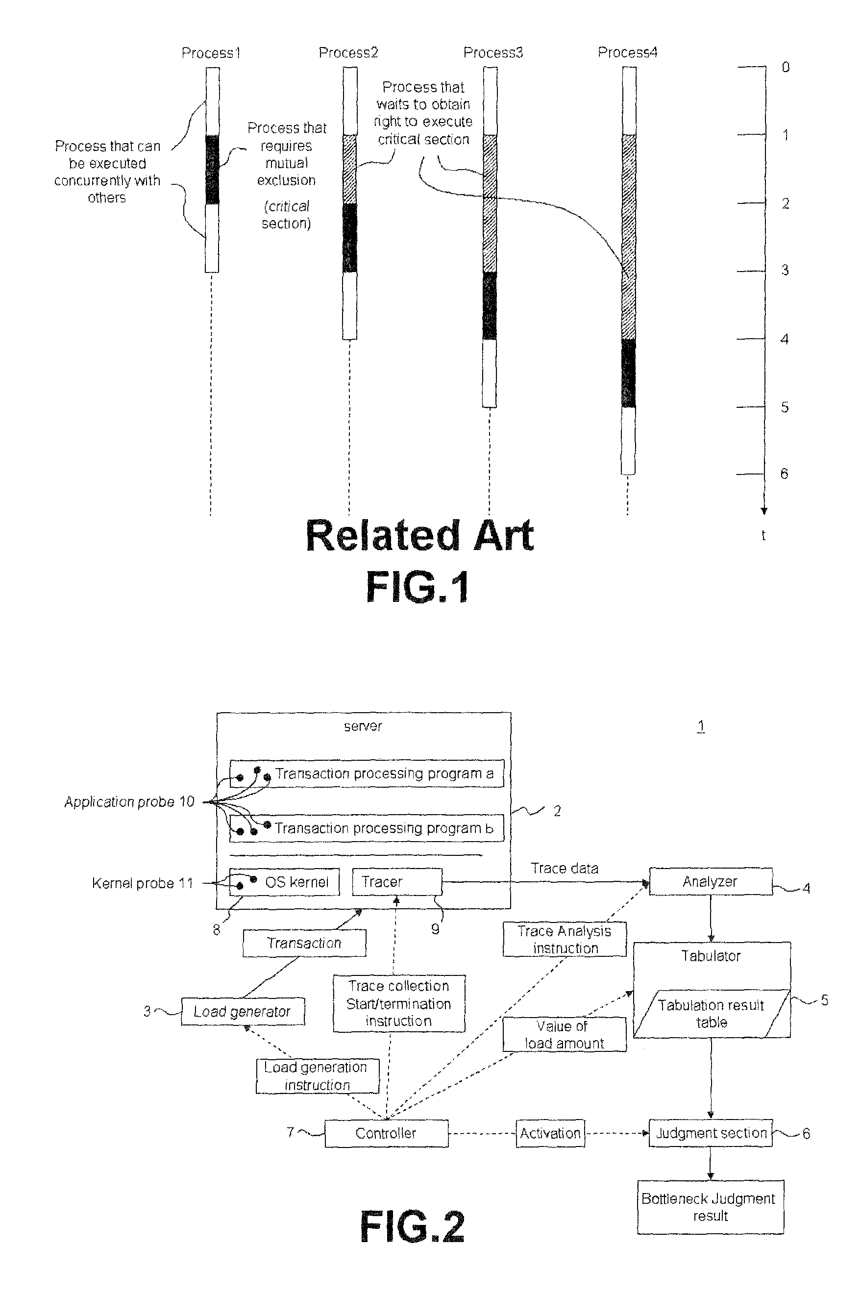
[0043]Hereinbelow, a conflicting sub-process identification apparatus 1 as an Exemplary embodiment of the present invention is described. As shown in FIG. 2, the conflicting sub-process identification apparatus 1 comprises a server 2, a load generator 3, an analyzer 4, a tabulator 5, a judgment section 6 and a controller 7.

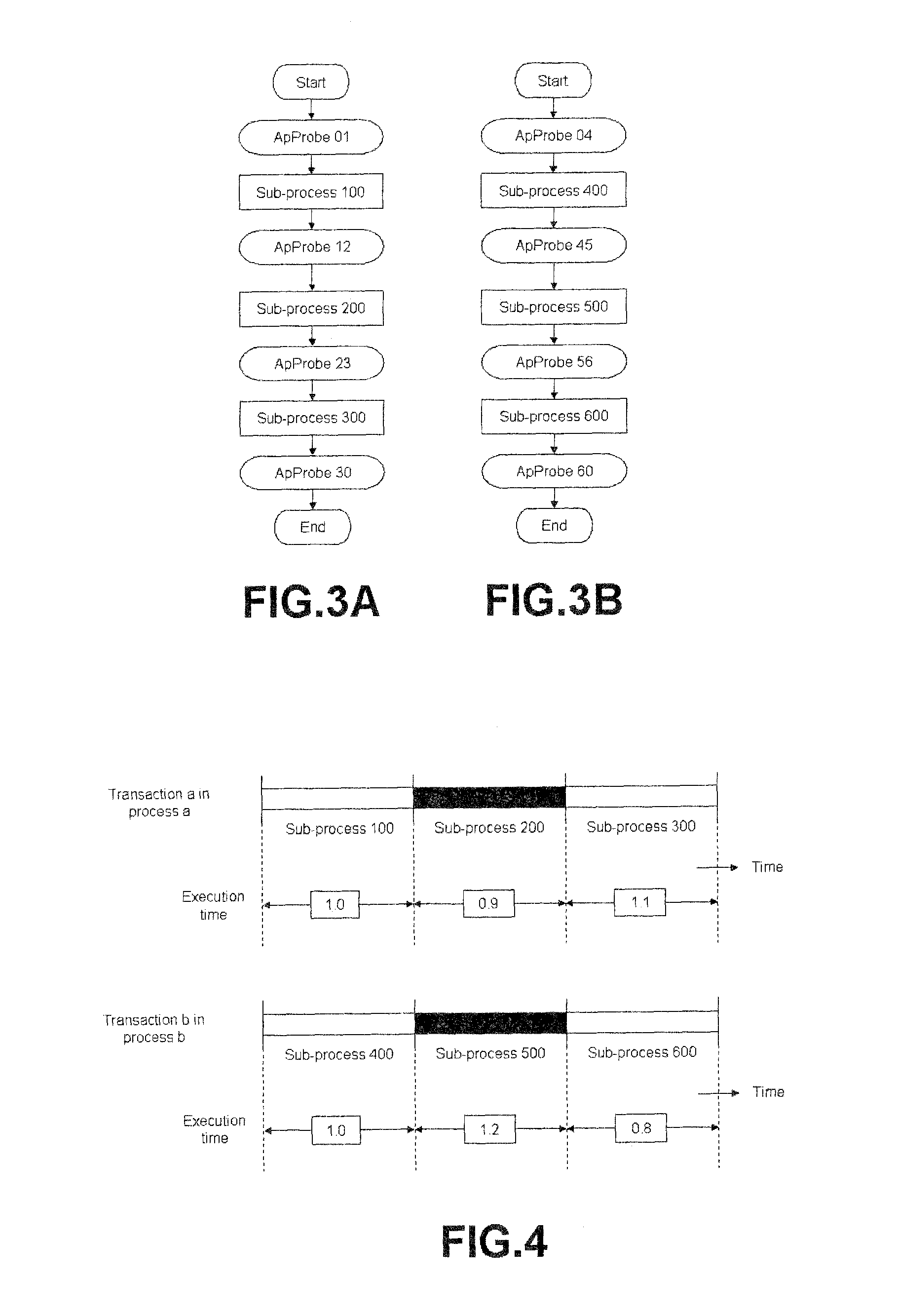
[0044]The server 2 is an object of the measurement. The operation of the server 2 is controlled by some program. And the server 2 includes a transaction processing program a, a transaction processing program b, an operating system (OS) kernel 8 and a tracer 9. The server 2 processes two types of transactions, a transaction a and a transaction b. Although the case of processing two transactions is used for the description in this embodiment, an actual server may process more than three types of transactions. A progr...


PUM


Abstract

A technique for identifying conflicting sub-processes easily in a computer system that processes a plurality of transactions in parallel is provided.In a conflicting sub-process identification method according to the present invention, a comparison is made between processing time periods for which transactions executed in parallel have conflicting parts and for which transactions executed in parallel do not have conflicting parts. This comparison is made for a plurality of transaction processing programs each comprising a plurality of sub-processes. Then, on the basis of correspondence relationships between performance indices obtained from the comparison result, conflicting combination of sub-processes competing for a resource are identified.

Description

BACKGROUND OF THE INVENTION[0001]1. Field of the Invention[0002]The present invention relates to identifying a part in a server where a plurality of processes competes for a resource. In particular, the present invention relates to a technique to identify conflicting processes in a server on the occurrence of a conflict attributable to concurrent processing of a plurality of transactions.[0003]2. Description of the Related Art[0004]A first related art is a technique described in Takashi Horikawa, “Performance Analysis of a Client-Server System Using Queueing Networks: A Case Study,” Int. Trans. Opl Res. Vol. 4, No. 3, pp. 199-209, 1997, and is a technique to evaluate the performance of a server that concurrently processes a plurality of transactions. In the first related art, an evaluation is made by using: basic performance data, which is the time spent on using a server resource (such as a CPU or a disk) for processing a single transaction; and a performance evaluation model based...

Claims


Application Information

Patent Timeline
Patent Type & Authority Patents(United States)
IPC IPC(8): G06F9/52G06F9/46
CPCG06F9/466G06F9/52
Inventor HORIKAWA, TAKASHI
Owner NEC CORP
Why Eureka
Try Eureka