Gas turbine exhaust diverter system duct guide rails

a technology of exhaust diverter system and guide rail, which is applied in the direction of heat exchanger casing, steam generation using hot heat carriers, lighting and heating apparatus, etc., can solve the problems of high mechanical high constraints on the closure device, and sealing problems, so as to simplify the mechanism and the tools, and reduce the amount of human resources required.

Inactive Publication Date: 2019-10-22
GE ENERGY PRODS FRANCE
View PDF25 Cites 0 Cited by
  • Summary
  • Abstract
  • Description
  • Claims
  • Application Information

AI Technical Summary

Benefits of technology

[0006]Thus, a purpose of the invention is to allow a change in the operating method of a simple cycle or a combined cycle thermal plant by simplifying the mechanism and the tools to implement this change as well as by reducing the human resources required. In other words, the invention proposes to simplify the maneuvering of the closure devices of the bypass sections of the exhaust system without risk to the maintenance operators or the components of the exhaust system.
[0007]Thus, an exhaust system is proposed for a gas turbine that may include a bypass duct for the turbine exhaust gas having a gas inlet section capable of receiving the exhaust gas from the turbine, a first section connected to the exhaust collector and a second section connected to the heat collection boiler, and detachable ducts respectively being opened and closed and selectively being fitted in the first and second sections so as to operate the exhaust system in a simple cycle mode or in a combined cycle mode. The bypass duct may include an assembly of at least one guide rail capable of guiding the ducts about the bypass duct. The exhaust system thus allows the handling and setting up of the detachable ducts on the bypass duct.

Problems solved by technology

The closure devices of these exhaust systems may be subjected to very high constraints due to the temperature differentials that may exist on either side of these devices.
Such temperature differentials may create very high mechanical constraints on the closure devices and may create sealing problems during operation.
Nevertheless, it was observed that the various flow bypass solutions provide either an expensive but rapid conversion mechanism or a less expensive conversion mechanism having a longer conversion time.
In fact, the most recent mechanisms that are used to maneuver the closure devices of the bypass sections of the exhaust systems may be relatively complex to implement and may require considerable human resources, for example, for the shifting of the various elements.

Method used


Image

  • Gas turbine exhaust diverter system duct guide rails
  • Gas turbine exhaust diverter system duct guide rails
  • Gas turbine exhaust diverter system duct guide rails

Examples


Embodiment Construction

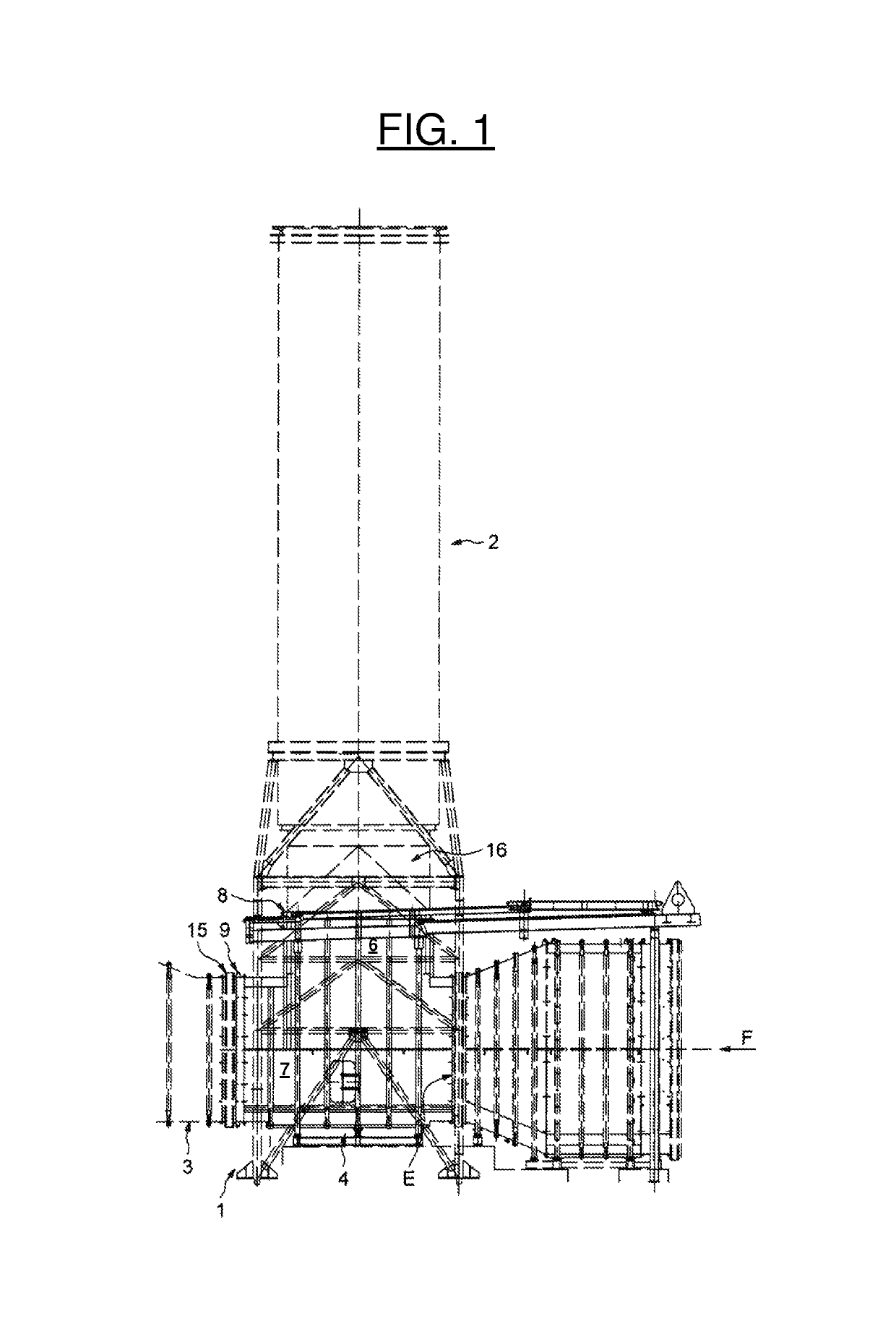
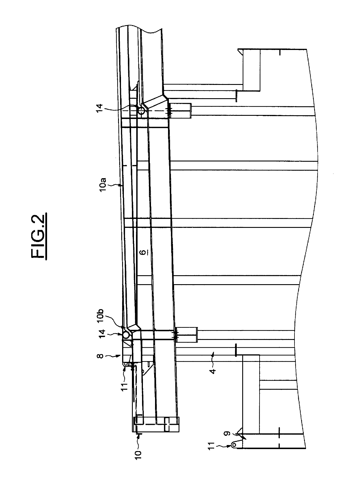
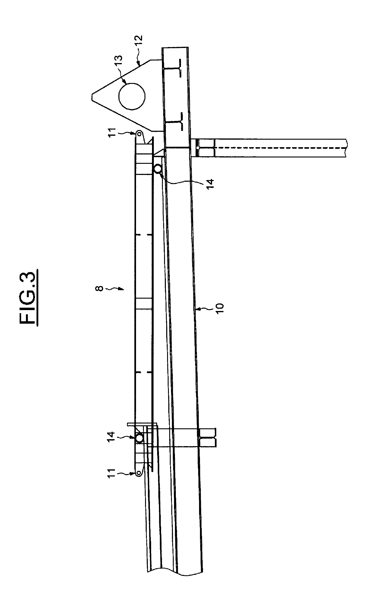
[0025]Referring now to the drawings, in which like numerals refer to like elements throughout the several views, FIGS. 1-4 illustrate an example of an exhaust system for a gas turbine as may be described herein, referred to by the general numeric reference 1. This exhaust system is meant to be positioned at the outlet of a gas turbine of a power plant to collect exhaust gases and guide the exhaust gases to an exhaust collector 2, in this instance, a chimney, when the gas turbine operates in a simple cycle or towards a heat collection boiler, whereof only an inlet 3 is shown. As is seen, the exhaust system may include a bypass duct 4 that internally provides a gas passage towards the chimney 2 and a gas passage towards the boiler 3. The bypass duct 4 thus has an inlet section E for the exhaust gas of the turbine that receives an incidental flow of gas according to arrow F, a first outlet section 6 for connection with the chimney 2, and a second outlet section 7 for connection with th...


PUM


Abstract

This gas turbine exhaust system provides a bypass duct having a gas inlet section capable of receiving the turbine exhaust gas, a first section for connection with an exhaust gas collector and a second section for connection with a heat collection boiler, detachable ducts respectively opened and closed, selectively fitted in the first and second sections, to operate the exhaust system in a simple cycle mode or in a combined cycle mode, and guide rails for guiding the ducts.

Description

TECHNICAL FIELD[0001]The present application and the resultant patent relate generally to gas turbine engines and more specifically relate to gas turbines operating in a simple cycle method, where the exhaust gases of the turbine may be collected by a gas exhaust collector and released to the atmosphere through a chimney, and in a combined cycle method, where the output gases may be led by an exhaust system to a heat collection boiler to produce steam which in turn may be provided to a steam turbine. Specifically, the present application relates to a gas turbine exhaust system with a bypass duct that directs the exhaust gas either into the atmosphere, in a simple cycle, or towards the collection boiler, in a combined cycle. The exhaust system may be reconfigured according to the operating phases or maintenance requirements of the turbine.BACKGROUND OF THE INVENTION[0002]When operating a turbine and when the heat collection boiler needs to be put out of order for maintenance, it may ...

Claims


Application Information

Patent Timeline
Patent Type & Authority Patents(United States)
IPC IPC(8): F01D25/30F28F9/02F16K11/065F22B1/18F16K3/02
CPCF01D25/30F28F9/028Y02E20/16F16K11/0655F22B1/1815F16K3/029
Inventor FERRARIS, ALAN
Owner GE ENERGY PRODS FRANCE
Why Eureka
Try Eureka