
Signal source localization using compressive measurements

a compression measurement and signal source technology, applied in the field ofsignal processing, can solve the problems of unduly increasing the cost, complexity and power consumption of the sensor, and the problem of other types of signal source localization applications, and achieve the effect of reducing the sampling ra

Active Publication Date: 2015-07-14
ALCATEL LUCENT SAS
View PDF7 Cites 3 Cited by
  • Summary
  • Abstract
  • Description
  • Claims
  • Application Information

AI Technical Summary

Benefits of technology

[0005]Illustrative embodiments of the present invention overcome one or more of the above-described drawbacks of conventional signal source localization techniques. For example, in a given one of these embodiments, only a single sensor of a plurality of sensors used in signal source localization operates at or above the Nyquist rate, while the remaining sensors of the plurality of sensors all generate compressive measurements at a substantially lower sampling rate through the use of compressive sampling. In another embodiment, all of the plurality of sensors used in the signal source localization can generate compressive measurements. The sensors generating the compressive measurements each take a much smaller number of samples within a given period of time than would a conventional sensor operating at or above the Nyquist rate, and can also transmit those samples to a processing device at a similar low rate. Moreover, the accuracy of the signal source localization result based on the compressive measurements is not adversely impacted.
[0008]The illustrative embodiments provide significant advantages over conventional approaches. For example, in one or more of these embodiments, the sensors generating compressive measurements can be implemented as simple, low-cost sensors that operate at low sampling rates, and therefore do not require significant hardware resources or exhibit high power consumption. This considerably facilitates the widespread deployment of sensor networks, particularly in remote locations with harsh conditions, or in other environments that are unsuitable for installation of complex and costly sensors.

Problems solved by technology

Conventional arrangements of this type are problematic, however, in that each of the sensors of the sensor network is generally required to operate at a sampling rate that is at or above the Nyquist rate, where the Nyquist rate denotes the minimum sampling rate required to avoid aliasing, which is twice the highest frequency of the signal being sampled.
The sampling and transmission operations therefore typically involve the use of significant hardware resources, which unduly increases the cost, complexity and power consumption of the sensors.
Similar problems exist in other types of signal source localization applications.

Method used


Image

  • Signal source localization using compressive measurements
  • Signal source localization using compressive measurements
  • Signal source localization using compressive measurements

Examples


Embodiment Construction

[0013]The present invention will be illustrated herein in conjunction with exemplary communication systems and associated sensor networks, processing devices and signal localization techniques. It should be understood, however, that the invention is not limited to use with the particular types of systems, devices and techniques disclosed. For example, aspects of the present invention can be implemented in a wide variety of other communication, sensor network or other processing system configurations, and in numerous alternative compressive sampling applications.

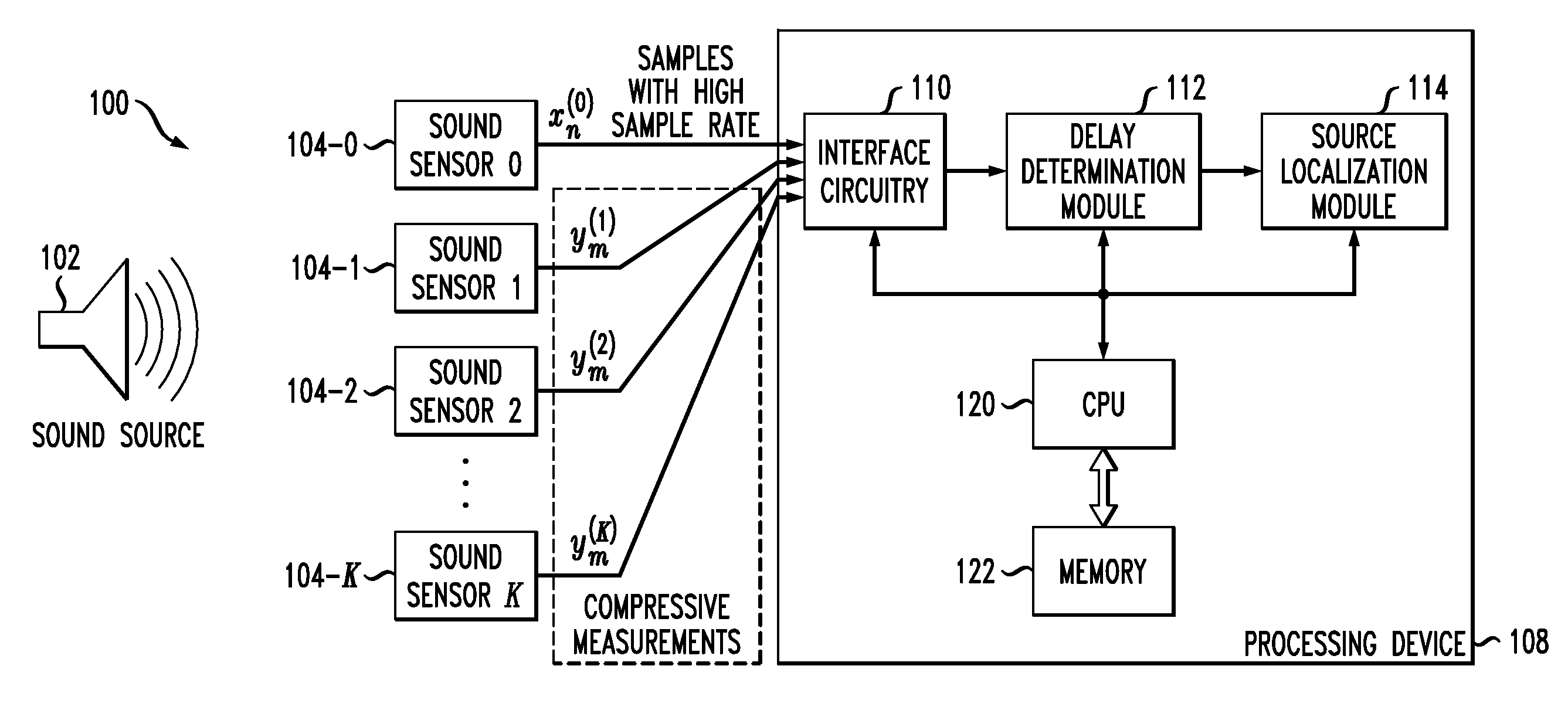
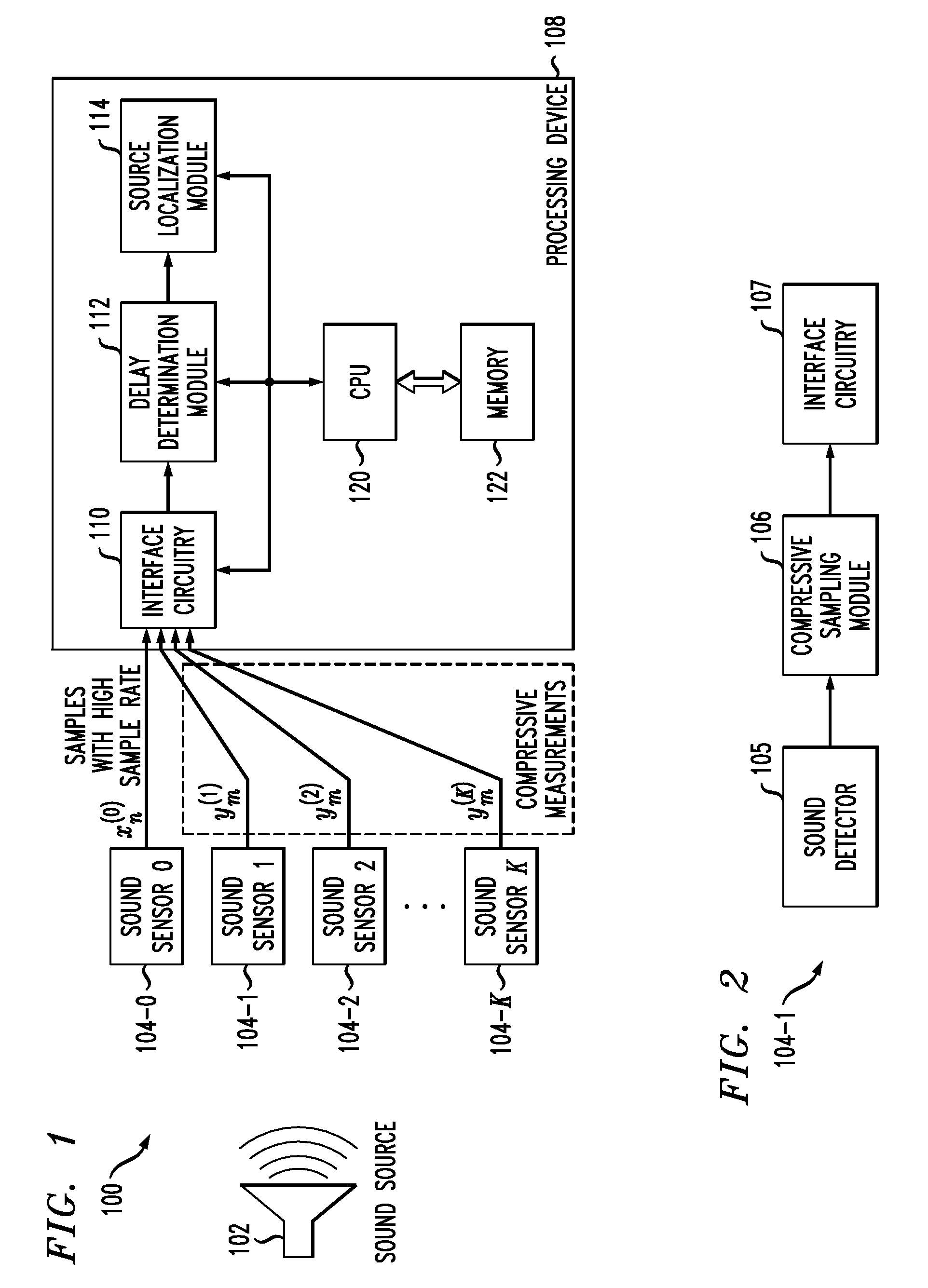
[0014]FIG. 1 shows a communication system 100 in which an acoustic signal from a sound source 102 is detected by each of a plurality of sound sensors 104-0, 104-1, 104-2, . . . 104-K. A designated subset of the set of K+1 sensors 104 generate respective compressive measurements, while at least one of the sensors 104 not in the designated subset generates a non-compressive measurement. More particularly, in the present embodim...


PUM


Abstract

In one aspect, a method for performing signal source localization is provided. The method comprises the steps of obtaining compressive measurements of an acoustic signal or other type of signal from respective ones of a plurality of sensors, processing the compressive measurements to determine time delays between arrivals of the signal at different ones of the sensors, and determining a location of a source of the signal based on differences between the time delays. The method may be implemented in a processing device that is configured to communicate with the plurality of sensors. In an illustrative embodiment, the compressive measurements are obtained from respective ones of only a designated subset of the sensors, and a non-compressive measurement is obtained from at least a given one of the sensors not in the designated subset, with the time delays between the arrivals of the signal at different ones of the sensors being determined based on the compressive measurements and the non-compressive measurement.

Description

FIELD OF THE INVENTION[0001]The present invention relates generally to the field of signal processing, and more particularly to signal source localization techniques.BACKGROUND OF THE INVENTION[0002]Signal source localization is an important signal processing function in a wide variety of different types of systems. For example, networks of sound sensors are often used to locate and track the source of an acoustic signal associated with a sound event in applications such as security and surveillance. In such arrangements, a signal in the form of a sound wave from a sound source is typically sampled at each of the sensors, and an algorithm is applied to the resulting samples in order to estimate the location of the source based on differences in the arrival times of the sound wave at each of the sensors.[0003]Conventional arrangements of this type are problematic, however, in that each of the sensors of the sensor network is generally required to operate at a sampling rate that is at...

Claims


Application Information

Patent Timeline
Patent Type & Authority Patents(United States)
IPC IPC(8): H04R3/00
CPCH04R3/005
Inventor JIANG, HONGMATHEWS, BOYD T.WILFORD, PAUL A.
Owner ALCATEL LUCENT SAS
Learn More