
Method for monitoring the operation of a wind energy plant and wind energy plant

a technology for wind energy plants and wind energy, applied in wind energy generation, mechanical equipment, machines/engines, etc., can solve problems such as large area danger to humans, animals and objects, and achieve the effect of improving the fit function and increasing the statistics

Active Publication Date: 2015-12-03
SIEMENS GAMESA RENEWABLE ENERGY SERVICE GMBH
View PDF6 Cites 22 Cited by
  • Summary
  • Abstract
  • Description
  • Claims
  • Application Information

AI Technical Summary

Benefits of technology

The patent describes a method for monitoring the vibrations of wind power plant rotor blades. The method uses a low sampling rate to register the vibrations, reducing the cost and processing speed. It also takes into account environmental parameters and operational parameters that affect the blades' vibration properties. The method uses a dedicated fit function for each monitored natural frequency, which is based on real or simulated vibration measurement data. The fit function is improved during ongoing operation by further measurements and increasing the statistics. The main technical effects of the patent include reducing costs and processing speed, improving accuracy, and better modeling of the rotor blades' vibration behavior.

Problems solved by technology

Here, inter alia, safety aspects include imbalances, resonances, dropping ice and material fatigue, which can likewise occur in rotor blades.
Ice accretion may already form at temperatures below 3° C. and, firstly, as additional mass, puts a strain on the rotor blades and, secondly, as a source for ice droppings, is a danger to humans, animals and objects over a large area.

Method used


Image

  • Method for monitoring the operation of a wind energy plant and wind energy plant
  • Method for monitoring the operation of a wind energy plant and wind energy plant
  • Method for monitoring the operation of a wind energy plant and wind energy plant

Examples


Embodiment Construction

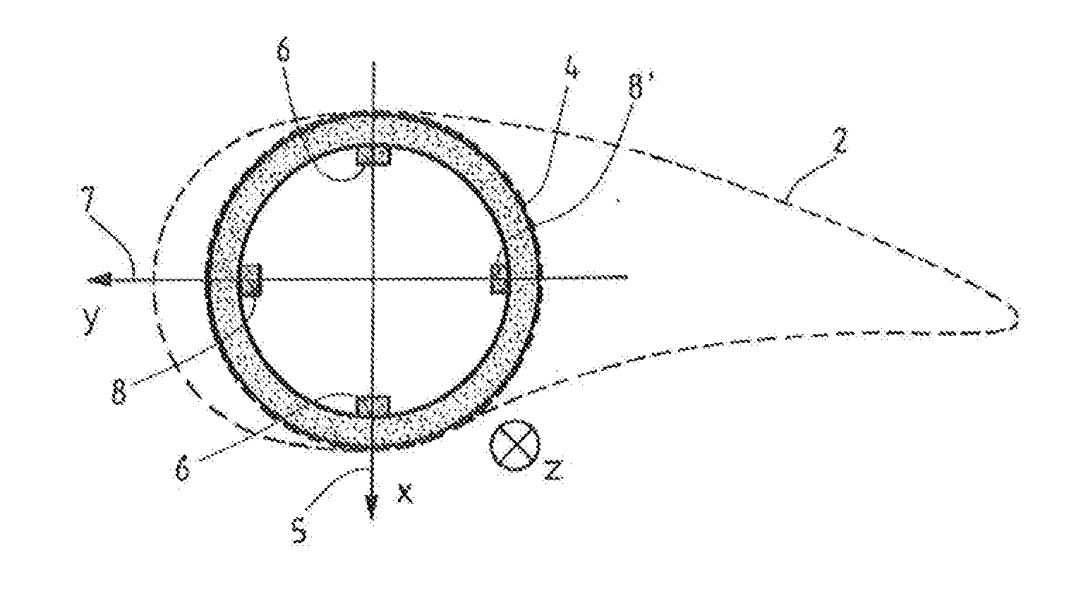
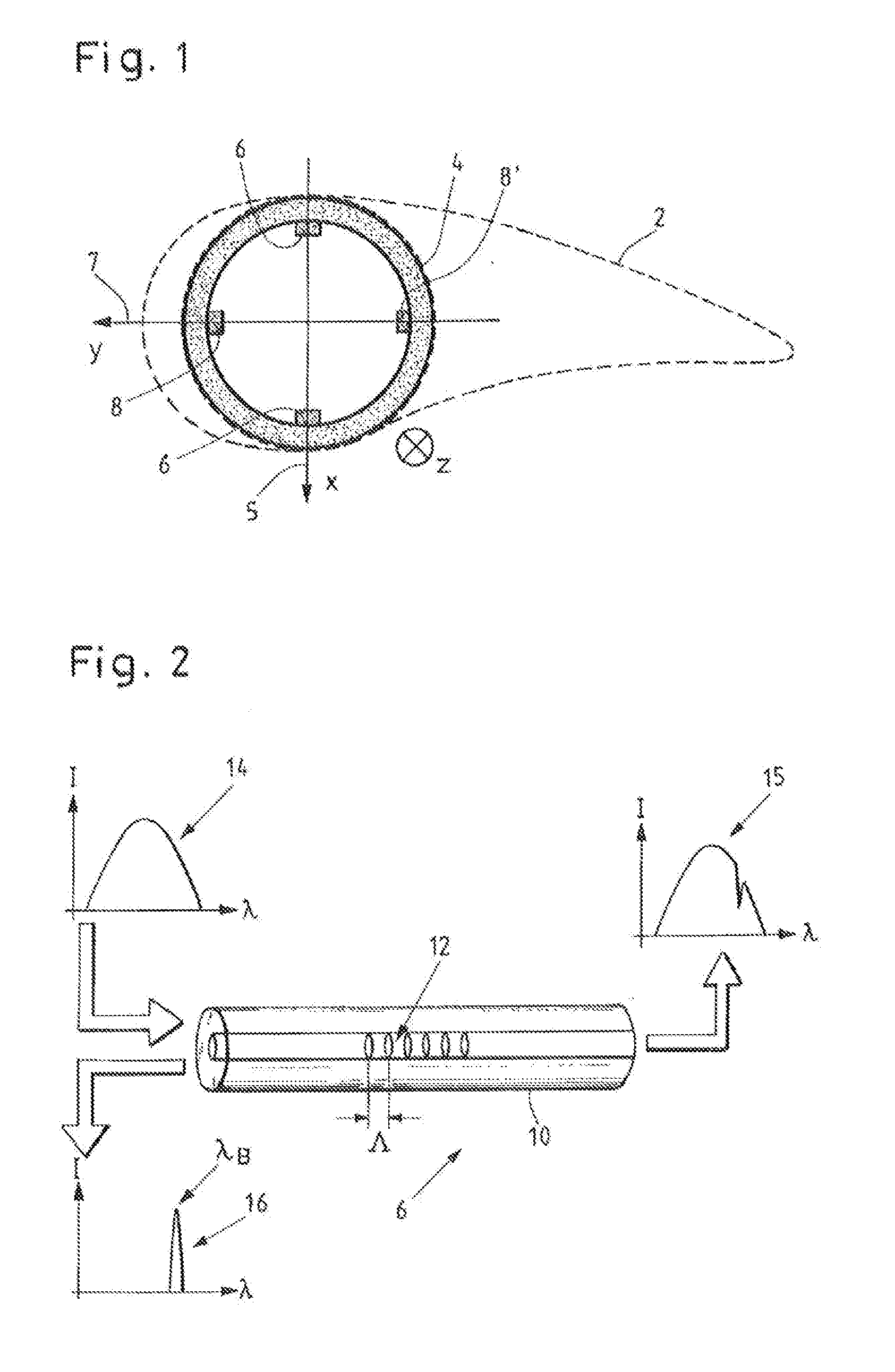
[0043]FIG. 1 schematically illustrates a cross section of a rotor blade 2. A profile contour in a central section is depicted using dashed lines. The rotor blade root 4 is depicted as a solid circle. A coordinate system has been plotted, wherein the x-axis points in the impact direction 5 from the suction side to the pressure side, whereas the y-axis points in the rotational direction 7 to the front edge of the profile. The z-axis points into the plane of the drawing toward the blade tip (not depicted here).

[0044]Four strain sensors 6, 6′, 8, 8′ are attached in the inner circumference of the rotor blade root 4, respectively two strain sensors 6, 6′ in the impact direction 5 and two strain sensors 8, 8′, in the rotational direction 7. Therefore, in general, one sensor of a sensor pair 6, 6′ and 8, 8′, respectively, is compressed and the other sensor is stretched when the rotor blade is bent. By way of example, the strain sensors 6, 6′, 8, 8′ can be fiber Bragg grating sensors.

[0045]F...


PUM


Abstract

A method for monitoring the operation of a wind energy plant having at least one blade angle adjustable rotor blade. Rotor blade vibrations are registered during operation by at least one measuring device, and at least one current natural frequency is established from the registered vibrations. At least one environmental parameter and / or at least one operational parameter, which influence the natural frequency of the rotor blade, is or are additionally registered. At least one natural frequency expected value dependent on the additionally registered parameter(s) and at least one confidence interval are calculated for the at least one established current natural frequency of the rotor blade, and whether the established current natural frequency lies within, or outside of, the confidence interval around the natural frequency expected value is monitored. Also disclosed is an operational control apparatus of a wind energy plant and a corresponding wind energy plant.

Description

CROSS-REFERENCE TO RELATED APPLICATIONS[0001]This application is a continuation of International Application No. PCT / EP2014 / 000149, flied Jan. 21, 2014, and claims priority to German Pat. App. No. 10 2013 202 261.1, filed Feb. 12, 2013.BACKGROUND OF INVENTION[0002]1. Field of Invention[0003]The invention relates to a method for monitoring the operation of a wind energy plant comprising a tower, a nacelle arranged on the tower and a rotor, which has at least one blade angle adjustable rotor blade, wherein rotor blade vibrations of the at least one rotor blade are registered during the operation of the wind energy plant by means of at least one measuring device and at least one current natural frequency of the at least one rotor blade is established from the registered rotor blade vibrations, wherein at least one environmental parameter and / or at least one operational parameter is or are additionally registered, which parameter or parameters influences or influence the natural frequen...

Claims


Application Information

Patent Timeline
IPC IPC(8): F03D7/02F03D11/00
CPCF03D7/0224F03D11/0091F03D7/0296F05B2260/84F05B2270/303F05B2270/32F05B2270/327F05B2270/328F05B2270/335F03D17/00F03D80/40F05B2270/325F05B2270/334F05B2270/808Y02E10/72F03D7/045
Inventor KRAMER, BERTIN
Owner SIEMENS GAMESA RENEWABLE ENERGY SERVICE GMBH
Learn More