Introducer assembly

a technology of introducer and assembly, which is applied in the field of introducer assembly, can solve the problems of damage or trauma to the vessel walls, and shift of devices, and achieve the effect of reducing or preventing jerking of medical devices or introducers

Active Publication Date: 2015-07-28
COOK MEDICAL TECH LLC +1
View PDF11 Cites 0 Cited by
  • Summary
  • Abstract
  • Description
  • Claims
  • Application Information

AI Technical Summary

Benefits of technology

[0009]Withdrawing the distal end of the carrier element simultaneously with the process of expansion of the medical device causes the distal end to be located within the medical device itself as this is being released from the introducer. The partly deployed medical device acts to place in the centre thereof and to support the distal end of the introducer in the middle of the lumen of the medical device during the deployment / withdrawal operation. As a result, the risk of the distal end of the introducer scraping against the wall of the vessel or of the medical device are avoided or minimized.
[0010]In the preferred embodiment, the restriction mechanism is such as to provide a small annular gap through which the medical device can expand.
[0011]Locating the restriction mechanism at the proximal end of the introducer, typically so as always to remain outside the patient, ensures that this mechanism need not be designed so as to be insertable endoluminally, which would severely affect the size and form permissible for the restriction device, the types of vessel where it could be used and the performance of the introducer. Furthermore, the distal end of the introducer can be kept of relatively simple construction and one which does not alter the trackability or pushability characteristics of the introducer compared to existing devices.
[0016]In another embodiment, the restriction element provides for an annular gap to be opened at the distal end of the sheath which has a width substantially the same as or slightly smaller than the thickness of the medical device carried on the introducer. In this embodiment, thus, the radial spacing between the carrier element and sheath is the same as or greater than the width of the annular gap. In this embodiment, the medical device will expand though the annular gap while contacting the surfaces of the sheath and dilator tip, which applies friction to the movement of the medical device, useful in reducing or preventing jerking of the medical device or introducer during the deployment operation.

Problems solved by technology

In some circumstances this can cause damage or trauma to the vessel walls and or shift the device from the position in which it was deployed.
There is also the risk of damage to the medical device.
Any movement or damage to the device can lead to an abortive medical procedure.

Method used


Image

  • Introducer assembly
  • Introducer assembly
  • Introducer assembly

Examples


Embodiment Construction

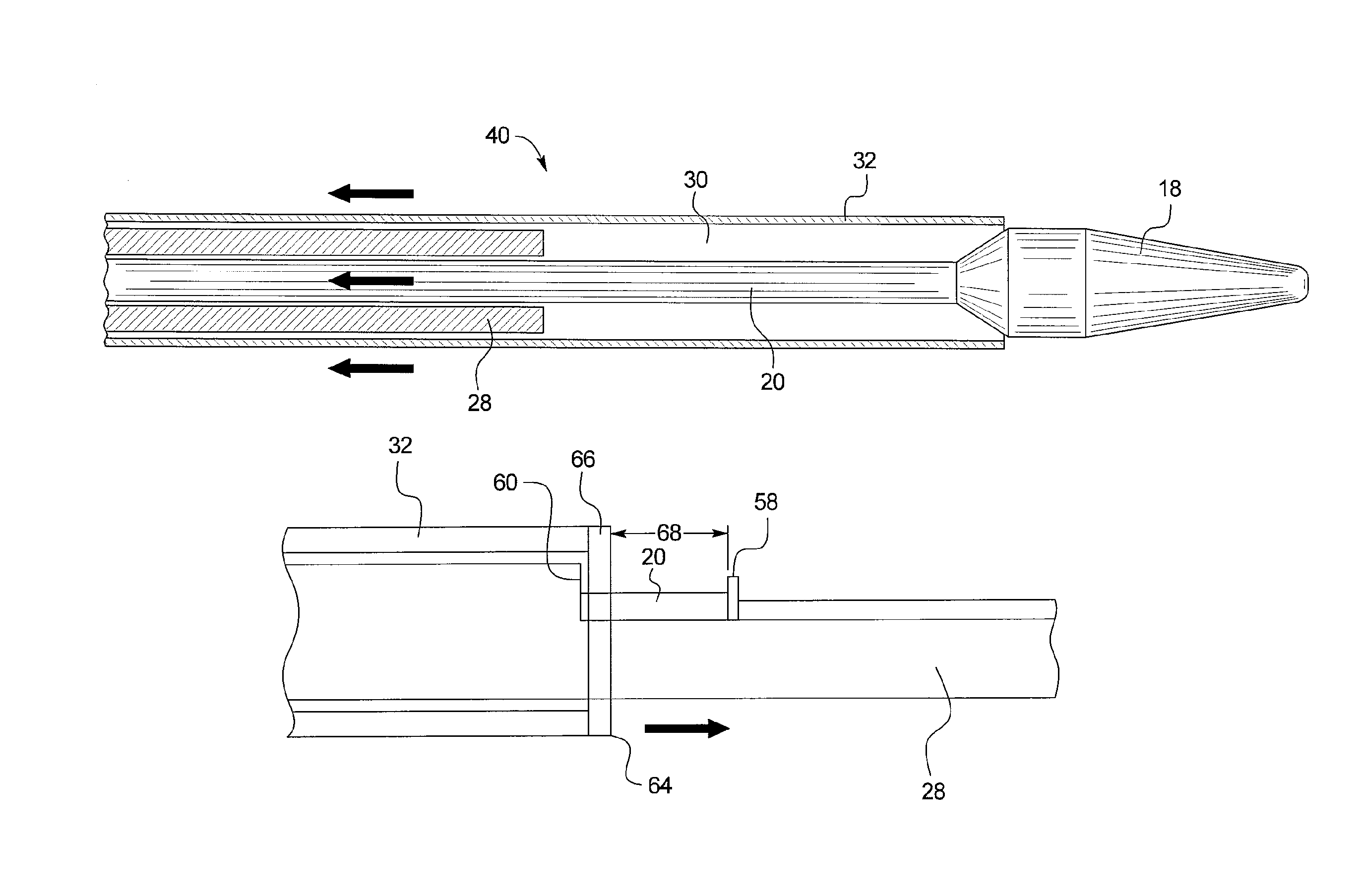
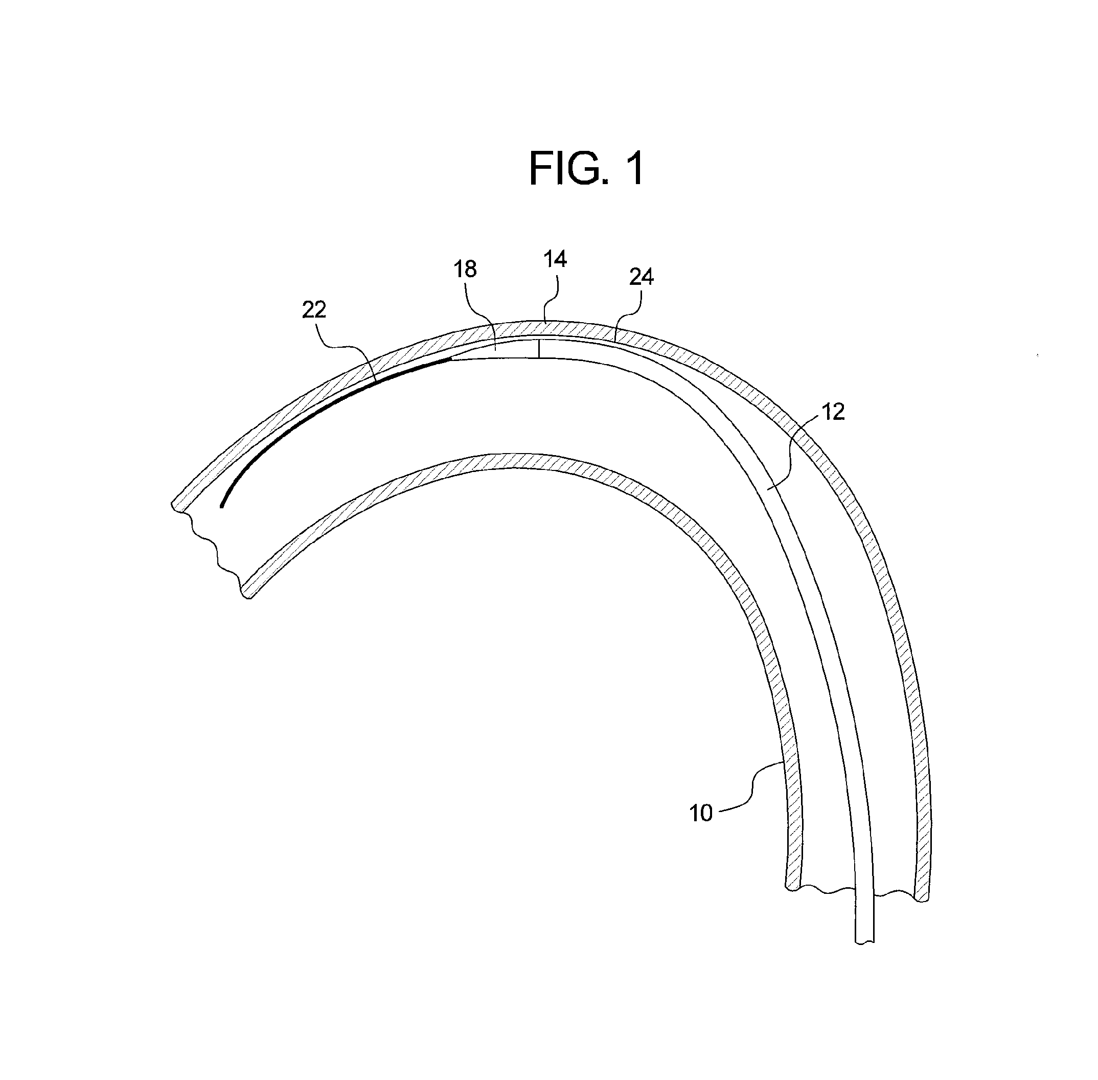
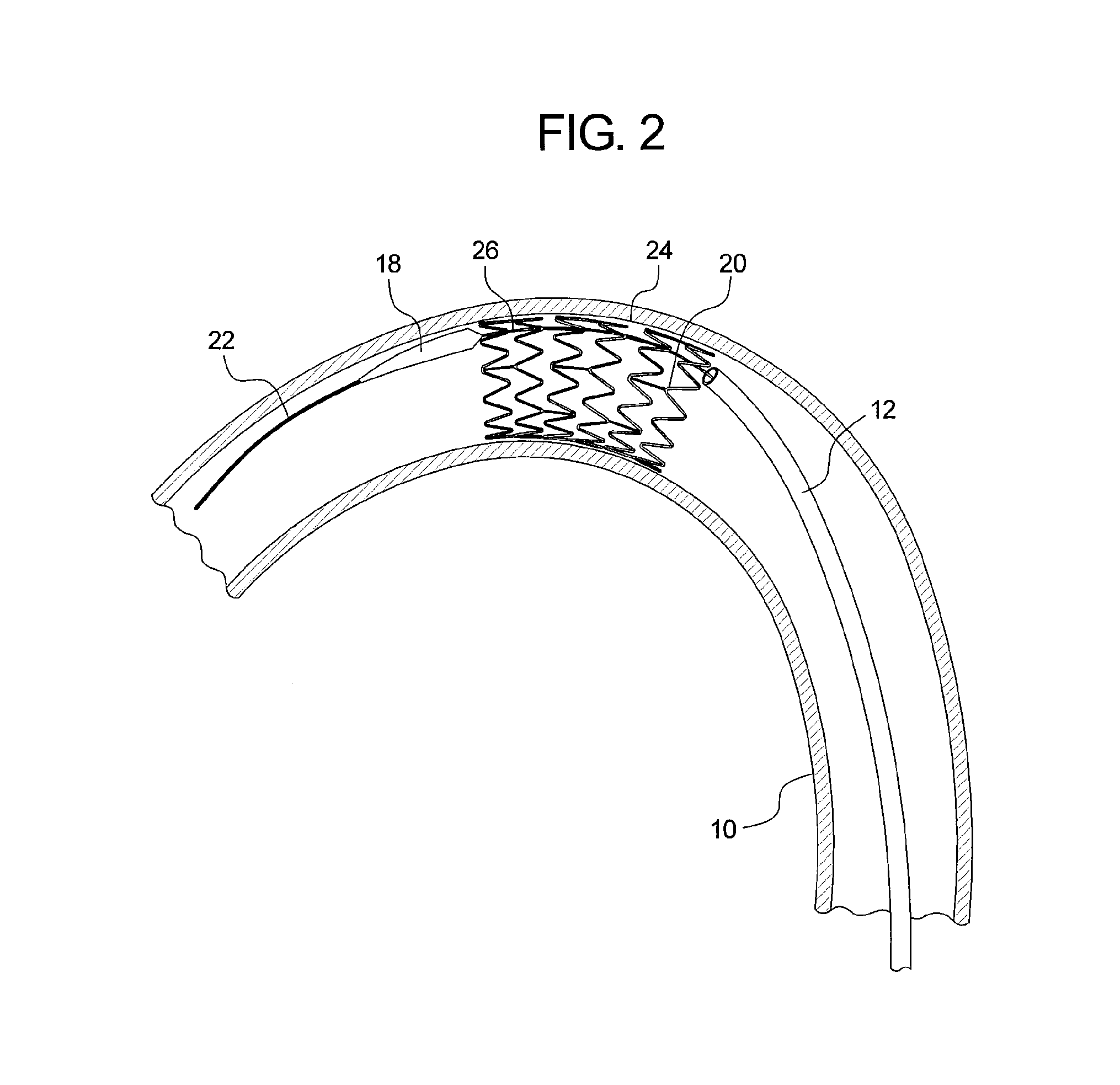
[0026]Referring to FIG. 1, there is shown an example of a curved vessel 10 representing an aortic section which may have the dimensions and a curvature equivalent to that of the aortic arch of a human. Within the vessel 10 there is located an introducer 12, the distal end 14 of which is located at or around the zone of greatest curvature of the vessel 10. The tip of the introducer 10 is provided with a flexible dilator tip 18, of known form. The dilator tip 18 is fixed to the distal end of a guide wire catheter 20 (visible in FIG. 2). The introducer 12 and dilator tip 18 are provided with an internal lumen which receives a guide wire 22, also of conventional form, for assisting in guiding the insertion and movement of the introducer through a patient's vessels.

[0027]The typical procedure for introducing the introducer 12 into a patient is by means of the well known Seldinger technique, in which the guide wire 22 is first inserted percutaneously into a patient's vasculature via a nee...


PUM


Abstract

An introducer assembly (40) for use in the deployment of implantable medical devices such as stents and stent grafts includes a carrier element (20), a dilator tip (18) located at the distal end of the carrier element (40) and sheath (32) movable between a device covering position and a device deployment position. In the device deployment position, a restricted annular gap (34) is created between the distal end (36) of the sheath (32) and the proximal end (38) of the dilator tip (18). The gap (34) is restricted by a restriction mechanism (50) located at the proximal, external end, of the introducer assembly (40). The gap (34) allows for the progressive deployment of the medical device from the introducer (40) and for simultaneous retraction of the dilator tip (18) thereby avoiding snagging of the dilator tip (18) against the wall of a patient's vessels and of the medical device.

Description

[0001]This application is a National Stage of International Application PCT / US2010 / 31413 filed Apr. 16, 2010, which claims the benefit of the filing date under 35 U.S.C. §119(e) of Provisional U.S. Patent Application Ser. No. 61 / 212,836, filed Apr. 16, 2009. The entirety of both applications is hereby incorporated by reference.TECHNICAL FIELD[0002]The present invention relates to an introducer assembly for use in the endoluminal deployment of implantable medical devices such as stents, stent grafts and other devices.BACKGROUND OF THE INVENTION[0003]The endoluminal introduction and deployment of a medical device such as a stent or stent graft into a patient is a well known procedure. The introducer assembly is typically in the form of a catheter assembly which includes at least guide wire, a guide wire catheter and an outer sheath. The medical device is carried at a distal end of the guide wire catheter and the assembly may also include a pusher element which is also carried on or is...

Claims


Application Information

Patent Timeline
Patent Type & Authority Patents(United States)
IPC IPC(8): A61F2/06A61F2/95A61F2/07
CPCA61F2/95A61F2/07A61F2002/9517A61F2/9517
Inventor HANSEN, PALLE M.
Owner COOK MEDICAL TECH LLC
Why Eureka
Try Eureka