Method for operating an air vehicle

a technology for air vehicles and airframes, applied in the direction of automatic actuation, aircraft navigation control, vertical landing/take-off, etc., can solve the problems of radical degradation of air vehicle performance, poor lift and high drag, and flight safety

Active Publication Date: 2019-05-07
ISRAEL AEROSPACE IND
View PDF4 Cites 1 Cited by
  • Summary
  • Abstract
  • Description
  • Claims
  • Application Information

AI Technical Summary

Benefits of technology

[0012](B) using the operating map for guidance, causing the air vehicle to operate at least within a low Reynolds numbers range corresponding to the operating map, such as to avoid or minimize risk of causing the air vehicle to operate at conditions of separated flow over the fixed wings.
[0078]According to at least some aspects of the presently disclosed subject matter, there is provided a method of operation of air vehicles, in particular for UAV's, that helps to avoid the region of unfavorable flow phenomena at low Reynolds numbers, helping to ensure safe and undisturbed flight of air vehicle.
[0084]According to at least some aspects of the presently disclosed subject matter, operation of the air vehicle from zero forward speed includes initially increasing the airspeed at a reduced or even negative angle of attack in order to surpass conditions of separated flow at minimum possible airspeed. Once the operating region of fully attached flow is penetrated (referring to the respective operating map), the air vehicle can safely increase the angle of attack and / or airspeed to realize high-lift capabilities of the wings in a fast an efficient manner.
[0087]Herein, the term “blunt leading edge” refers herein to increased thickness and increased local radius of the forward portion of the aerofoil that prevents formation of suction peak at high angles of attack and produces a rounded pressure distribution at the leading edge of the aerofoil.
[0088]Herein, the term “mild stall” refers to a type of stall that is characterized by almost constant level of the lift at post-stall domain and is associated with slowly creeping trailing edge separation that moderates the rate of lift losses at high angles of attack, typically resulting in an approximately constant lift coefficient (within about 5% to 10% of the maximum lift coefficient for at least about 5° after the stall angle of attack).
[0091]High lift, mild-stall aerofoils according to aspects of the presently disclosed subject matter are generally characterized by relatively high maximum lift relative to conventional mild stall aerofoils, while retaining and enhancing mild stall characteristics in the wide range of post-stall angles of attack. High lift, mild-stall aerofoils according to aspects of the presently disclosed subject matter comprise a blunt leading edge that substantially prevents formation of suction peak at high angles of attack, and can further comprise a highly cambered aft portion of the aerofoil that produces slowly creeping trailing edge separation as angle of attack is increased. Without being subject to theory, the combination of continuous lift build-up at the forward portion of such aerofoils with slowly progressing trailing edge separation produces the feature of mild stall at high level of maximum lift and provides significant advantage relative to conventional MS-aerofoils.

Problems solved by technology

Such phenomena include separated flow over the wings at low Reynolds numbers, including laminar leading edge stall and the burst of laminar separation bubble, which can sometimes distort the aerodynamics characteristics of the air vehicle, leading to problems of flight safety and radical degradation of air vehicle performance including poor lift and high drag.
In such small aircraft, the relatively low final airspeed after the stage of acceleration, combined with small wing chords, can correspond to relative small Reynolds numbers within the low Reynolds number range corresponding to the unfavorable flow phenomena domain, which conventionally leads to the aforesaid problems.

Method used


Image

  • Method for operating an air vehicle
  • Method for operating an air vehicle
  • Method for operating an air vehicle

Examples


Embodiment Construction

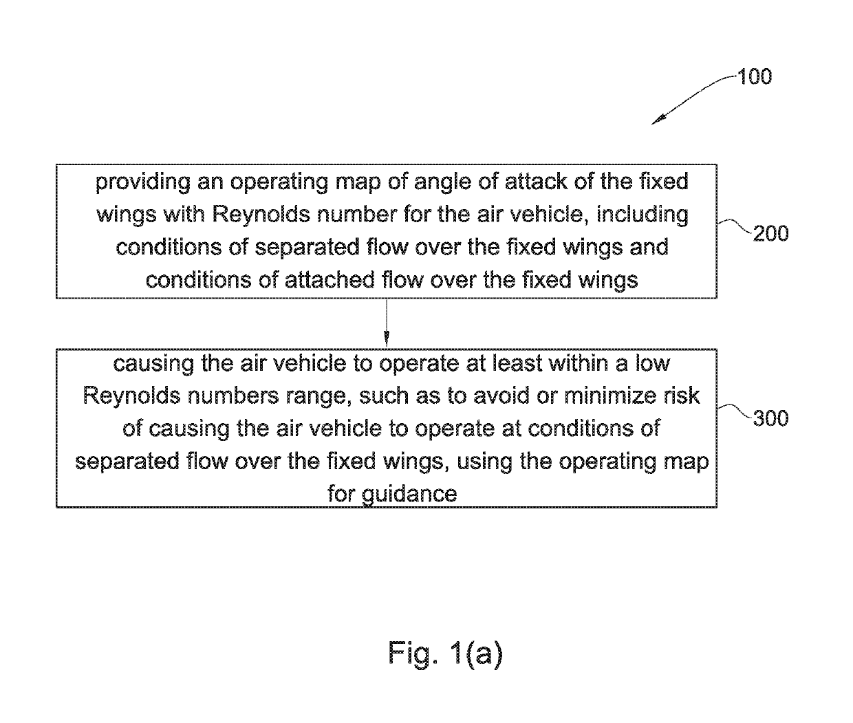
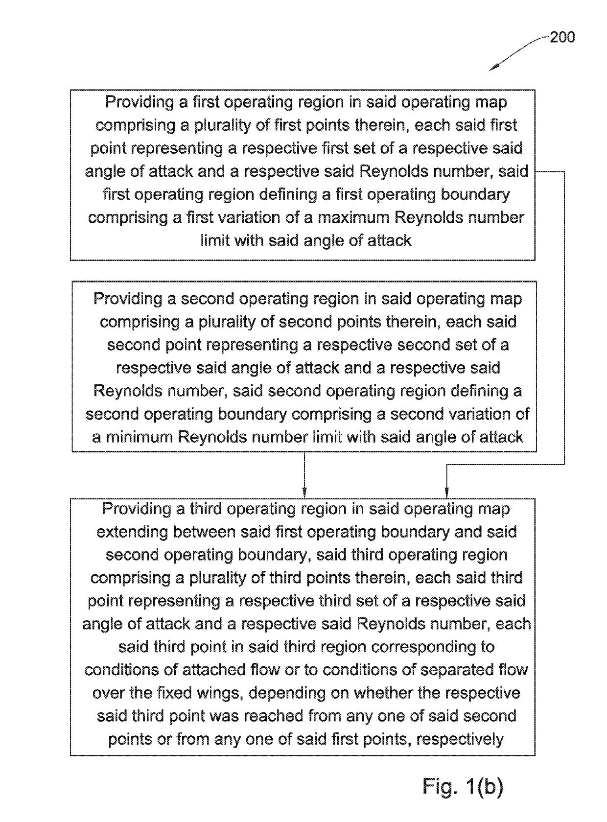
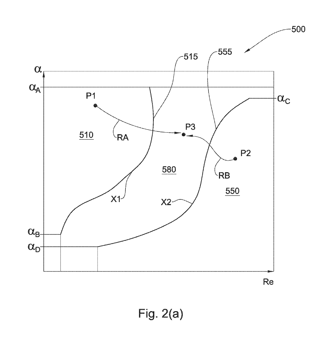
[0126]Referring to FIG. 1(a), a method for operating an air vehicle having fixed wings, according to a first example of the presently disclosed subject matter, generally designated 100, comprises the following general steps:[0127]Step 200˜providing an operating map of angle of attack of the fixed wings with Reynolds number for the air vehicle, including conditions of separated flow over the fixed wings and conditions of attached flow over the fixed wings[0128]Step 300˜causing the air vehicle to operate at least within a low Reynolds numbers range corresponding to the operating map, such as to avoid or minimize risk of causing the air vehicle to operate at conditions of separated flow over the fixed wings, using the operating map for guidance.

[0129]Step 300 can be of particular significance during certain critical phase in the flight envelope of the air vehicle, for example take-off or landing for conventional type air vehicles, including STOL air vehicles. Referring to FIGS. 3(a) to...


PUM


Abstract

Methods are provided for operating an air vehicle having fixed wings. Such methods include the step of providing an operating map of angle of attack associated with the fixed wings with Reynolds number, including conditions of separated flow over the fixed wings and conditions of attached flow over the fixed wings. Such methods also include the step of using the operating map for guidance, causing the air vehicle to operate at least within a low Reynolds numbers range corresponding to the operating map, such as to avoid or minimize risk of causing the air vehicle to operate at conditions of separated flow over the fixed wings.

Description

TECHNOLOGICAL FIELD[0001]The presently disclosed subject matter relates to methods of operating air vehicles and to air vehicles thus operated.PRIOR ART[0002]References considered to be relevant as background to the presently disclosed subject matter are listed below:[0003]U.S. Pat. No. 7,992,827[0004]U.S. Pat. No. 8,109,473[0005]Acknowledgement of the above references herein is not to be inferred as meaning that these are in any way relevant to the patentability of the presently disclosed subject matter.BACKGROUND[0006]Conventional aircraft accelerating during ground run at take-off from zero airspeed to lift-off airspeed, encounter very low Reynolds numbers at the start of acceleration Similarly, VTOL VSTOL and STOVL aircraft transitioning from hovering vectored flight to aerodynamic flight also essentially accelerate from zero forward airspeed to cruising airspeed, for example, and similarly encounter very low Reynolds numbers at the start of acceleration.[0007]At such very low R...

Claims


Application Information

Patent Timeline
Patent Type & Authority Patents(United States)
IPC IPC(8): B64C39/02B64C13/16B64C3/14B64C29/00B64D43/02B64C15/12
CPCB64C39/024B64C3/14B64C13/16B64C15/12B64D43/02B64C29/00Y02T50/12B64C2201/084B64C2201/104Y02T50/10B64U30/10B64U70/70
Inventor SHEPSHELOVICH, MICHAELABRAMOV, DANNYKLEIN, YONATAN
Owner ISRAEL AEROSPACE IND
Why Eureka
Try Eureka