Moving cleanout for reciprocating conveyor system

a conveyor system and moving cleanout technology, applied in the field of conveyor systems, can solve the problems of allowing a certain amount of material to pass (or leak past), sometimes buried end of the tarp, and affecting the overall cleaning function of the tarp, so as to improve the overall cleaning function

Active Publication Date: 2015-07-28
KEITH MFG
View PDF12 Cites 10 Cited by
  • Summary
  • Abstract
  • Description
  • Claims
  • Application Information

AI Technical Summary

Benefits of technology

[0012]More specifically, the pair of wing members are laterally mounted relative to each side of the headboard member. Each wing member is connected to the headboard member in a manner so that one is free to at least partially swing about an axis in a relatively unrestricted way. A flexible material like belting, or another kind of material, creates the free-floating action of the wing. In this manner, each wing can easily adjust to the kinds of variations in the lateral sidewalls that are typical to common trailers, as an example.
[0017]The flexible sheet can be made or dimensioned so that it is slightly wider than the distance between the sidewalls. This allows the lateral edges of the sheet to fold slightly in the region where trailer wall meets floor, to assist in the clean out function.
[0018]Other features included as part of the cleanout apparatus involve improvements that help return the apparatus to its original position in the trailer after the trailer load is emptied; and certain other refinements that help adjust the apparatus to the size of the trailer and improve its overall clean sweep function.
[0019]Among other things, the apparatus includes a rail member mounted to an outer surface of the wing that cooperates with a ramp or ramp member mounted to the container sidewall. The rail member is in alignment with the ramp member, the latter being near the container's end. As the leading edge of the wing slides against the ramp member, it is initially deflected inwardly and then passes over the ramp, like a bump. At that point, the rail member on the wing comes to rest on the ramp and holds the wing's baffle portion a fixed distance from the sidewall, preventing the leading edge from flaring outwardly relative to the container's end as at least part of the cleanout apparatus protrudes out from the container (at the end of the unloading process).
[0021]Another refinement involves placing adjustment brackets on opposite sides of the apparatus to adjust its width to different variations in container width. One of the overall advantages to the design is that it provides a modular unit that is easy to disassemble for shipping, but easy for the purchaser to assemble and adjust the unit to the dimensions of an existing trailer with the floor already installed.
[0023]The area of the sheet has to be great enough to create enough static frictional contact area so that the floor will not slip underneath the sheet as the floor moves the load. With the wing design described above, the dynamic frictional forces between the wings and sidewalls are reduced sufficiently so that the size of the sheet can be reduced. In effect, this means the sheet can be shortened so that it terminates at or just beyond the leading edges of the wings. When the apparatus reaches the end of its path of travel, a shorter length of the sheet hangs over the trailer's end and is less likely to be buried by some of the unloaded material.

Problems solved by technology

One of the problems with this design is that the end of the tarp is sometimes buried in the pile of unloaded material sitting on the ground.
Sometimes truck drivers will roll the truck forward to simply pull the tarp out of the load—which creates the same kind of problem.
A different problem associated with prior art systems is that they have a tendency to allow a certain amount of material to pass (or leak past) their lateral edges during the unloading process.
Poor cleanout along the lateral edges of the cleanout system is more of a problem for loads like gravel or sand, as examples, because left-over material from one load may contaminate the next load involving a different kind of material.
It is undesirable to have sand from one load mixed with asphalt in the next, as an illustrative example.

Method used


Image

  • Moving cleanout for reciprocating conveyor system
  • Moving cleanout for reciprocating conveyor system
  • Moving cleanout for reciprocating conveyor system

Examples


Embodiment Construction

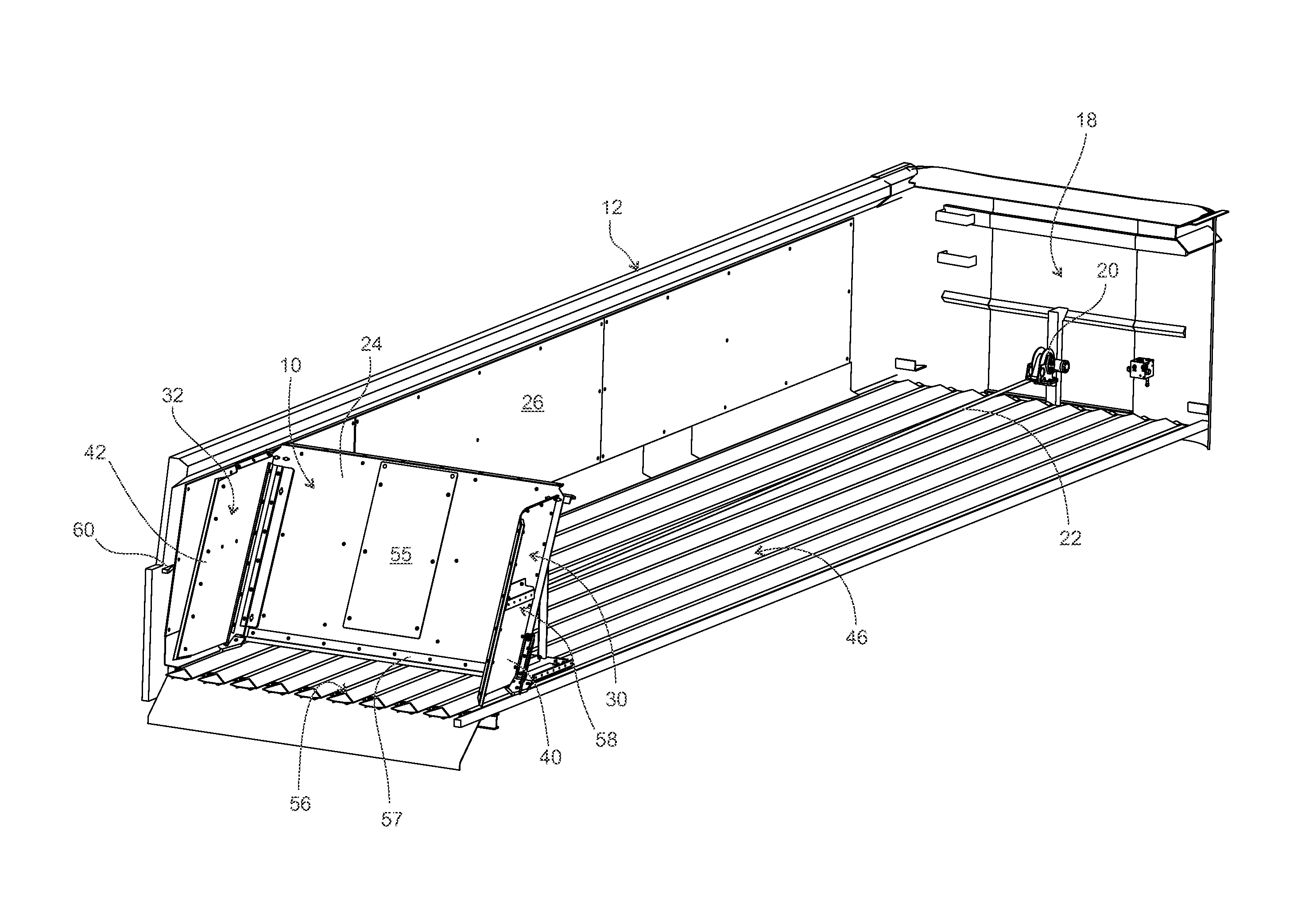
[0040]Referring now to the drawings, and first to FIG. 1. Shown generally at 10 is a moving headboard system (“moving headboard”) constructed in accordance with the invention.

[0041]In FIG. 1, the headboard 10 is shown at the aft end of a conventional trailer, indicated generally by arrow 12. This type of trailer 12 would be very familiar to a person having involvement with the trucking industry and knowledge about how reciprocating floor systems are built into the floor beds of trailers.

[0042]Trailers of this type are typically pulled by semi-trucks or the like. In the figure, the trailer has a rear door 14 that is hinged to the back. As is common, the door 14 swings up when the trailer is unloaded. Also, as is common, the load is inched off the trailer 12 by the built-in reciprocating floor slat system. The load, in this case, is schematically illustrated at 16. It could be a pile of gravel, as a non-limiting example, although systems of this type are used to haul many different ki...


PUM


Abstract

The invention disclosed here is a moving headboard for use in connection with a reciprocating floor slat system. It is particularly well-suited for use in connection with load-hauling trailers that have built-in reciprocating floor slat conveyors for unloading the trailer. Trailers of this kind are used in lieu of hydraulic lifts and involve inching the load off the trailer. The moving headboard sweeps the trailer floor clean during the unloading process.

Description

TECHNICAL FIELD[0001]The invention disclosed here generally relates to conveyor systems that are known as reciprocating floor slat systems. More particularly, the invention relates to a moving headboard that cleans the interior floor surface and wall of a truck trailer, or similar walled container, that is unloaded via a built-in reciprocating floor slat system.BACKGROUND OF THE INVENTION[0002]Reciprocating floor slat conveyors typically involve a set of load-supporting slats that all move together in one direction, and then return, one-third at a time, in the other direction. Because the dynamic frictional surface contact area between slat surfaces and load is less during slat return, the load is inched along by the conveyor apparatus as the slats move back and forth. Floor slat reciprocation is usually always driven by hydraulics, with some variation in unloading speed, depending on different variables.[0003]Reciprocating floor slat systems are often built into truck trailers that...

Claims


Application Information

Patent Timeline
Patent Type & Authority Patents(United States)
IPC IPC(8): B60P1/00B60P1/14
CPCB60P1/006B60P1/00
Inventor COOK, JOHNSTOUT, KENNETHJACKSON, DANIELFOSTER, RANDALL MARK
Owner KEITH MFG
Why Eureka
Try Eureka