
Pipe hanger assembly

a technology of pipe hangers and assembly parts, which is applied in the field of pipe hangers, can solve the problems of preventing access to the structure's environmental system, corroding or breaking, and major disadvantages of slab foundations, and achieves the effect of reducing the exposure of the pipe to the corrosive environmen

Inactive Publication Date: 2015-07-28
LACOUR DONNA E +1
View PDF23 Cites 14 Cited by
  • Summary
  • Abstract
  • Description
  • Claims
  • Application Information

AI Technical Summary

Benefits of technology

[0009]It is another object of the invention to provide a pipe hanger that minimizes exposure of the pipe to corrosive environment.

Problems solved by technology

However, slab foundations have a major disadvantage—they prevent access to the structure's environmental systems.
Water and sewage pipes lead to disaster if they corrode or break.
In some places, piping is buried under the ground below the slab and should the pipe becomes clogged or corroded an expensive excavation must take place to remove the damaged segment of the pipe.
In some areas, a problem exists where slabs settle or drop in elevation over a period of time.
This problem is particularly acute in low lying areas, or in areas which have poor soil conditions.
These pipes can settle, crack and produce explosions.
As the soil settles, the conventional hangers corrode and break, leaving the pipe unsupported.
As a consequence, the pipes below the slab bend, crack, and deteriorate.
Main sewer lines can back up causing considerable damage to the house.
In time, these nails will become loose, release the pipe hangers and the deterioration will start again.
Needless to say this process is time consuming and expensive.

Method used


Image

  • Pipe hanger assembly
  • Pipe hanger assembly
  • Pipe hanger assembly

Examples


Embodiment Construction

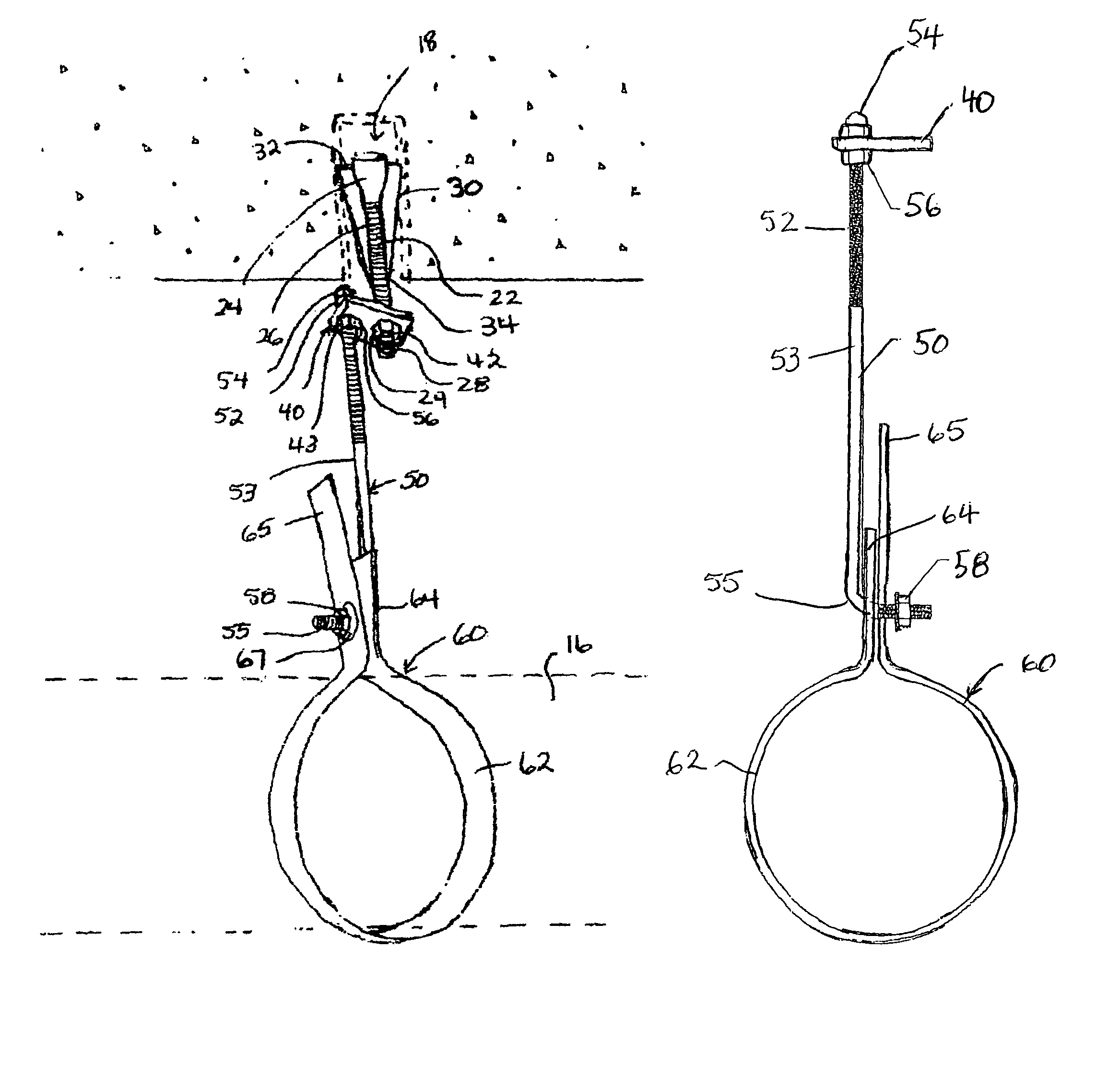
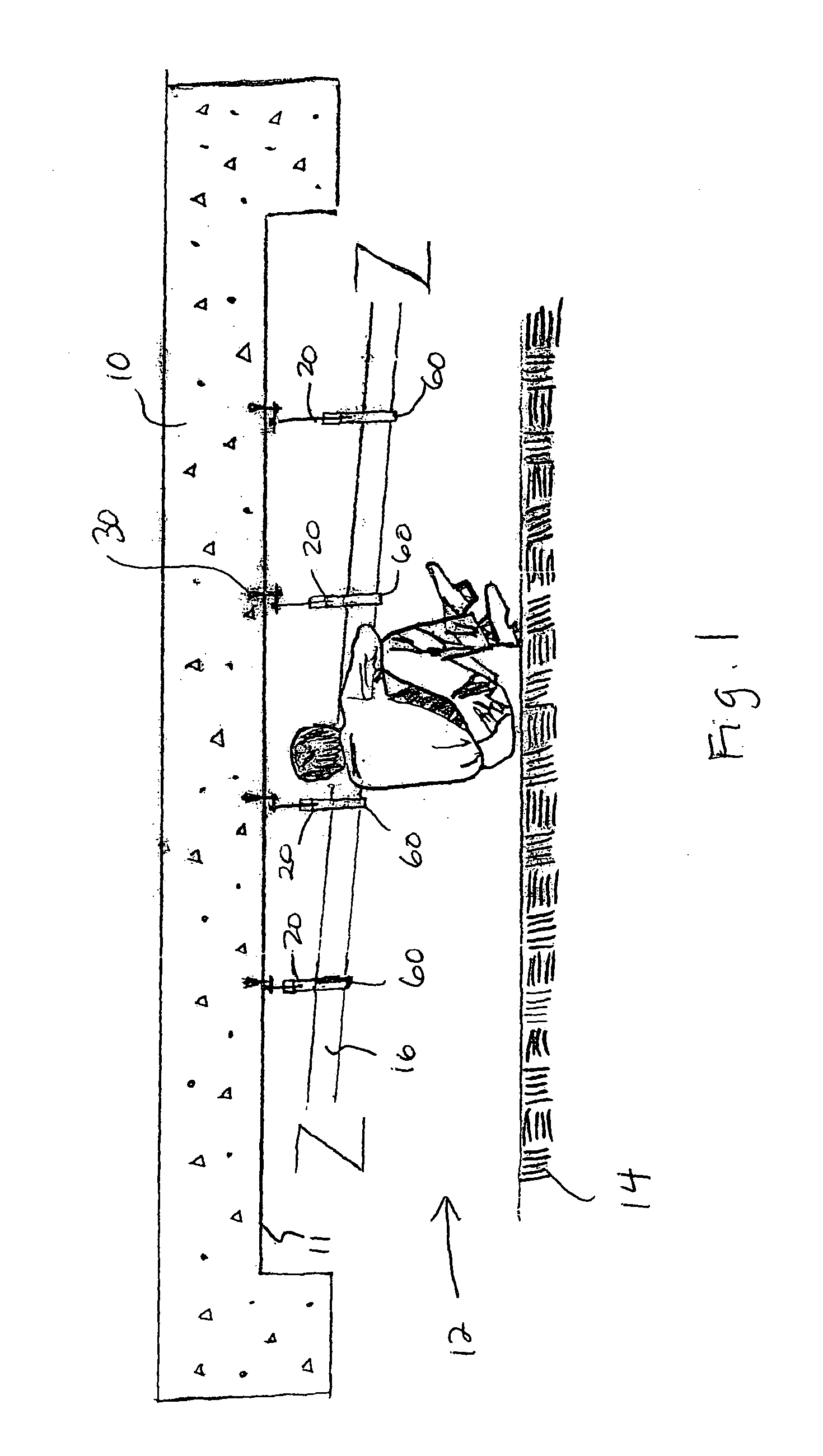
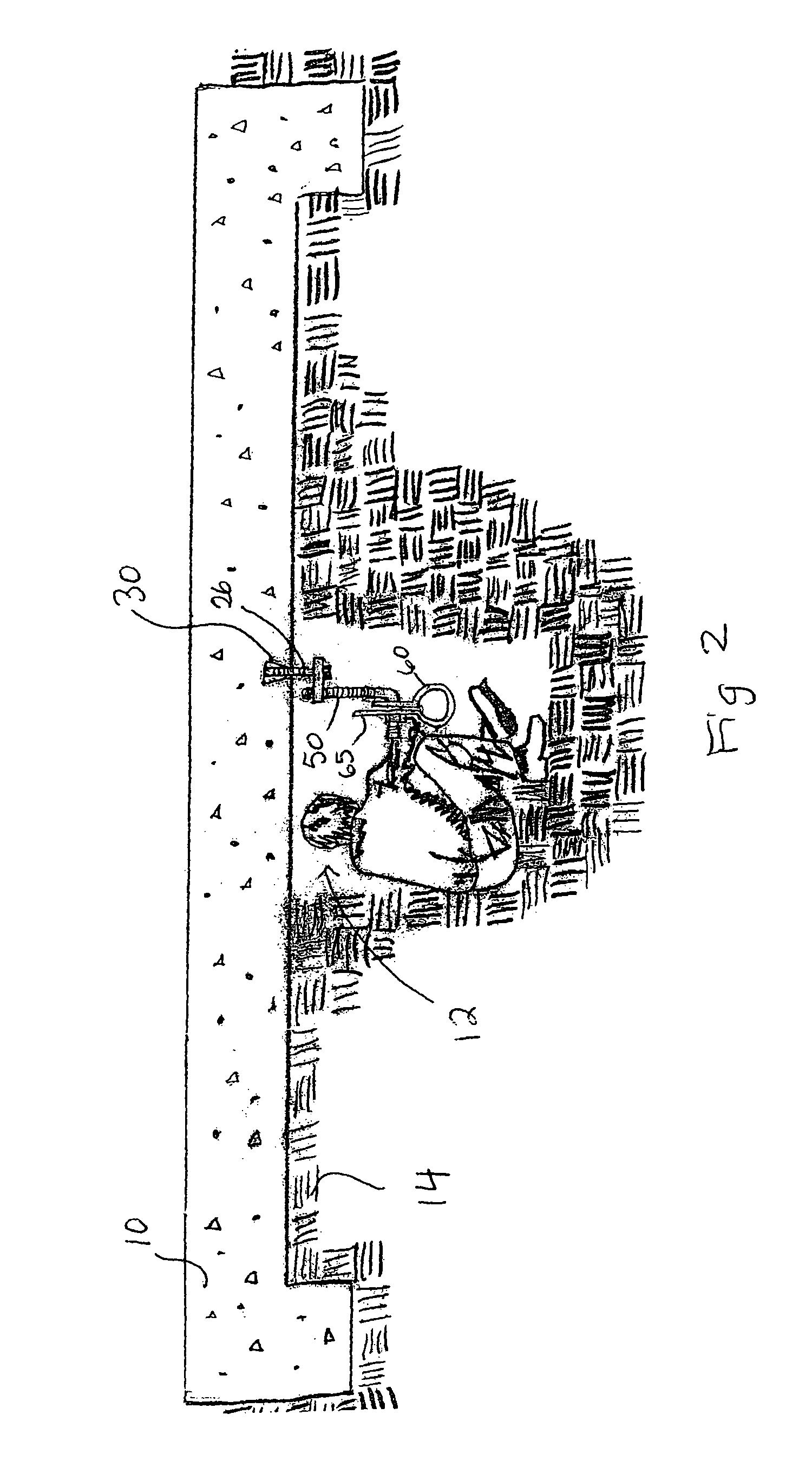
[0017]Turning now to the drawings in more detail, numeral 10 designates a slab or foundation that can be made of concrete or reinforced concrete depending on the structure. Although not shown, it is assumed that a structure, such as a house, rests on the foundation 10. An elongated trench 12 is formed in the soil 14 below the foundation 10. A pipe 16 extends within the trench 12 a distance below a bottom surface 11 of the slab 10. A plurality of grooves 18 is formed in the slab 10, with the grooves 18 extending upwardly from the bottom edge 11 of the slab 10. The grooves 18 can be punched in the slab 10 a distance from each other, for instance with an interval of about six feet. Of course, the distance between the grooves 18 can be modified depending on the weight of the pipe to be supported below the slab 10.

[0018]The pipe 16 is supported by a plurality of pipe hanger assemblies 20 according to the present invention. The hangers 20 provide support for the pipe 16 so that it does no...


PUM

PropertyMeasurementUnit
distanceaaaaaaaaaa
axial rotationaaaaaaaaaa
longitudinal dimensionsaaaaaaaaaa

Abstract

A pipe hanger for supporting a pipe below an overhead support, such as a slab foundation, is disclosed. A plurality of grooves is formed in the bottom of the slab foundation. A conical wedge is frictionally engaged with each groove to secure a first threaded suspension rod to the slab foundation. A second threaded J-shaped suspension rod is operationally connected to the first suspension rod through a connector plate, in relation to which the suspension rods can axially rotate. A pipe engaging loop is connected to the second suspension rod. The pipe engaging loop can be adjusted vertically and horizontally to accommodate natural position of the pipe.

Description

BACKGROUND OF THE INVENTION[0001]The present invention relates to pipe hangers for suspending a pipe from an overhead support, and more particularly to a pipe hanger that is configured for suspending a pipe beneath slab foundations of concrete and reinforced steel construction.[0002]In the construction of homes, office buildings and other such structures, it was and still is common to use a foundation of reinforced concrete prior to construction of the building superstructure. Slab-on-grade foundations are more common in warmer climates or where the soil is mostly clay. Some claim that termite issues may be less of a concern with this type of foundation, because of a lack of wood supports and empty spaces leading from the ground to the house itself. Such foundations are less expensive than elevated foundations with a crawl space or a basement.[0003]However, slab foundations have a major disadvantage—they prevent access to the structure's environmental systems. Either the electrical ...

Claims


Application Information

Patent Timeline
Patent Type & Authority Patents(United States)
IPC IPC(8): E21F17/02F16L3/00F16L3/133F16B13/06
CPCF16L3/133F16B13/065Y10T29/49826E04B1/4157E04C5/122E04G21/185
Inventor LACOUR, DONNA E.ELLSWORTH, ALEXANDER JOHN
Owner LACOUR DONNA E
Learn More