Wave energy conversion device for desalination, ETC

a wave energy and desalination technology, applied in the direction of piston pumps, fluid couplings, rotors, etc., can solve the problems of low efficiency of system operation, low efficiency of fuel supply, and inability to produce the high pressure that might be necessary for efficient desalination and other high pressure uses. , to achieve the effect of minimizing the exposure to wave action and low profil

Inactive Publication Date: 2006-04-04
KOBASHIKAWA ALVIN +1
View PDF58 Cites 123 Cited by
  • Summary
  • Abstract
  • Description
  • Claims
  • Application Information

AI Technical Summary

Benefits of technology

[0005]It is therefore a principal object of the present invention to provide a wave energy conversion device that can operate at high efficiencies and maintain efficient operation despite tidal variations. In particular, it is desired to provide an impulse-type “wave motor” design that is leveraged to generate high output fluid pressures suitable for desalination by reverse osmosis and other uses.
[0015]The platform may be elevated above the seabed on pier structures, or may be made adjustable in height above the seabed. The high-pressure fluid output may be conducted to shore for use in a shore-based plant. The coupling of the panel to the lever arm may be made adjustable to adjust the position of the panel in the subsurface area despite tidal variations. The pump may have an intake for intake seawater that is buoyant or floats on the surface of the sea. Preferably, the pump is combined with the desalination unit on the platform so as to have a compact and low profile for minimizing exposure to wave action. The high pressure output of the device may also be used for producing electricity, cogeneration systems, pumping cold water from the sea depths for air-chilling systems, recirculating water to cooler depths for heat exchange uses, and pumping compressed air or other fluids.

Problems solved by technology

However, while the prior art devices are designed to produce long traverse motion (stroke) for energy conversion, they do not produce the high pressures that might be necessary for efficient desalination and other high pressure uses.
Desalination of seawater for potable, irrigation, and other consumption uses is often required in remote regions that lack an electrical power infrastructure or where fuel supply is expensive and difficult to maintain.
However, by employing successively staged energy conversion steps, these systems tend to operate at low efficiencies and have difficulty maintaining operation despite tidal variations.

Method used


Image

  • Wave energy conversion device for desalination, ETC
  • Wave energy conversion device for desalination, ETC
  • Wave energy conversion device for desalination, ETC

Examples


Embodiment Construction

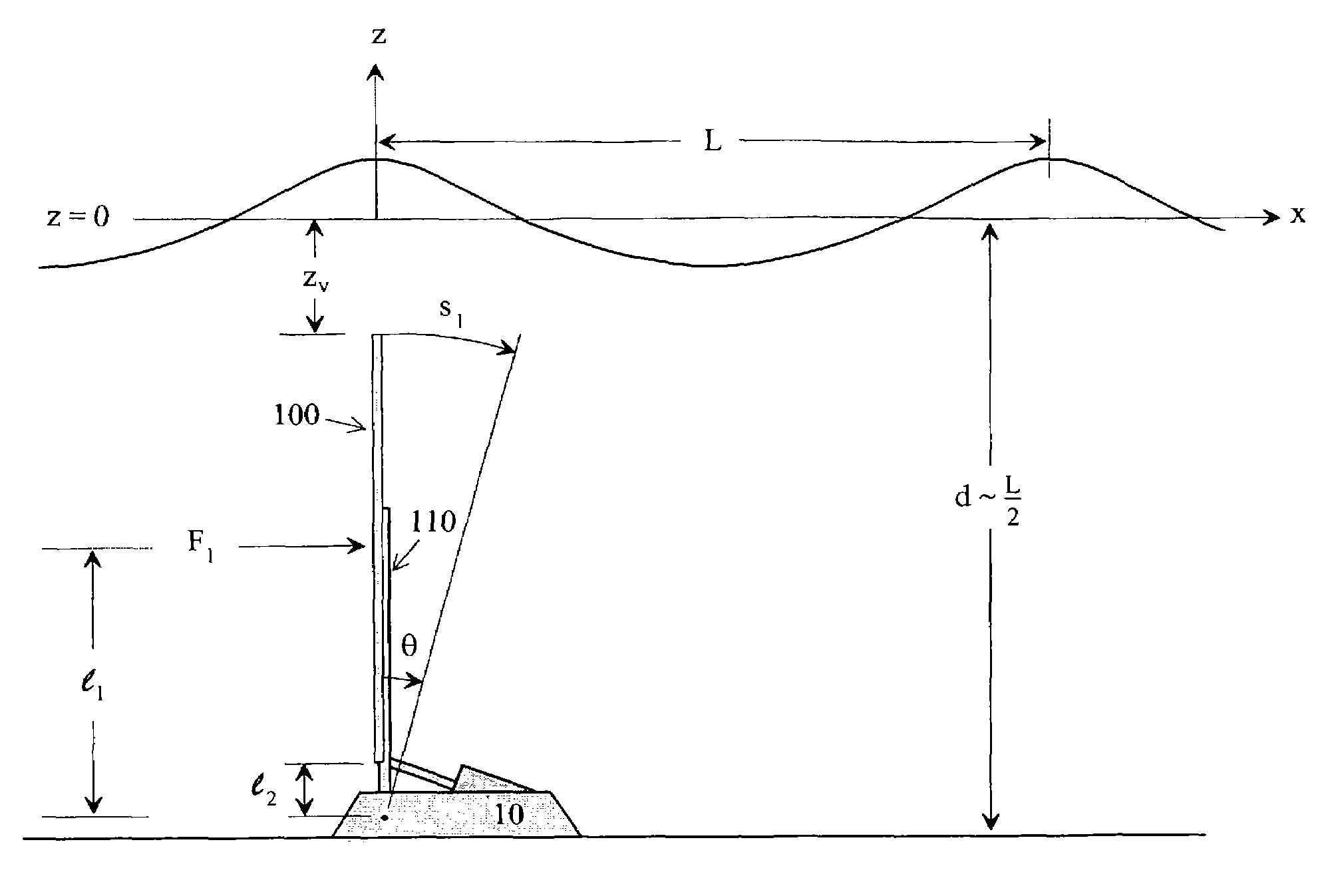
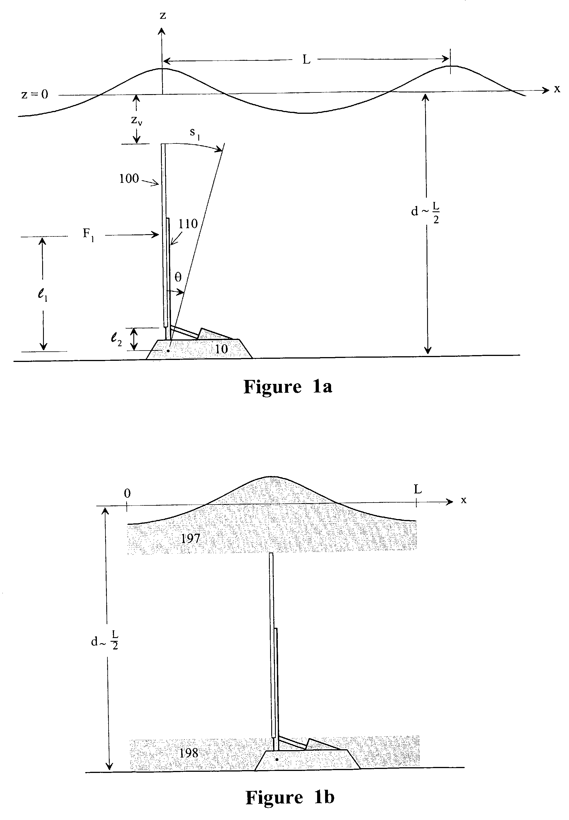
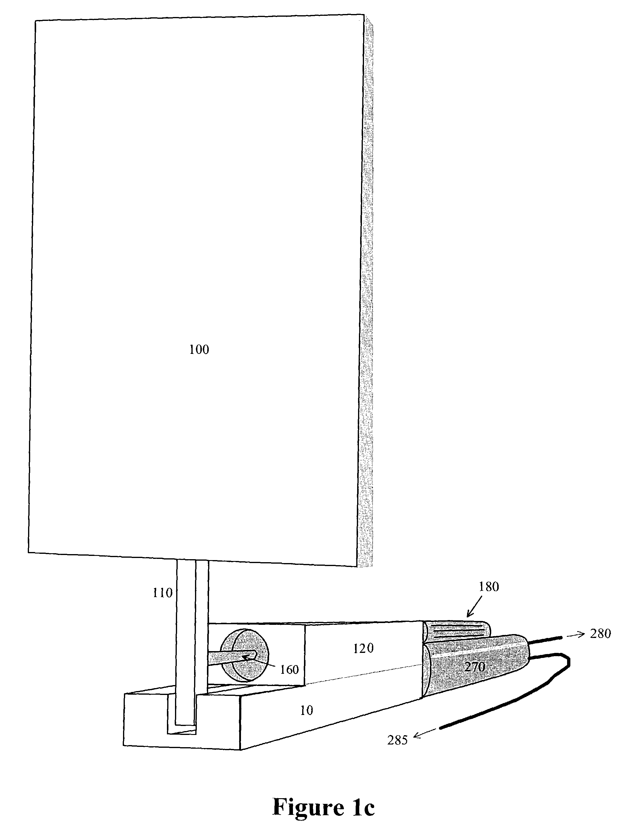
[0025]Illustrative examples of a wave energy conversion device in accordance with the present invention are described in detail below. In a preferred application, the system utilizes wave energy as a source of power to drive a membrane-type reverse osmosis desalination process by either compressing seawater or brackish water. The principle of impulse-type wave energy conversion is employed to generate the required pressures to drive the reverse osmosis process. A particularly advantageous impulse-type “wave motor” structure is employed to produce efficient desalination operation. However, it is to be understood that the principles of the invention disclosed herein may be applied equivalently to other types of impulse-type wave energy conversion structures.

[0026]From wave theory, water particle movements due to wave energy flux occur within a depth of L / 2, where L is the wavelength of the wave. The water depth is measured from the still water level to the seabed. The depth of water i...


PUM


Abstract

An impulse-type “wave motor” employs a seabed-mounted or supported structure mounting a wave energy absorbing panel on a hinged lever arm for reciprocation motion to obtain optimal absorption of wave energy from wave motion in the sea. For deepwater wavelengths of L, the panel is optimally positioned in a region within L / 2 depth from the sea surface. The panel motion is coupled by a connecting rod to a fluid pump which generates a high-pressure fluid output that may be used to drive a reverse osmosis desalination unit or to produce other useful work. Seawater or brackish water may be desalinated through reverse osmosis membranes to produce water quality for consumption, agricultural, or other uses. The submerged operating environment of the device in a region of one-half the design wavelength provides the maximum available energy flux and forced oscillations. The pump may be of the positive-displacement piston type, plunger type, or multi-staging driver type, or a variable volume pump.

Description

[0001]This U.S. patent application claims the priority of U.S. Provisional Application No. 60 / 395,359 of the same inventors filed on Jul. 11, 2002.TECHNICAL FIELD[0002]This invention generally relates to an energy conversion device powered by a renewable energy source, and more particularly, to a device that converts wave energy to supply driving pressures for desalination and other uses.BACKGROUND OF INVENTION[0003]In recovering wave energy from a body of water, many impulse type devices (energy absorbers) have been proposed. The general structure of an impulse type device used to capture wave energy discussed herein typically has a panel attached to a lever arm with a hinged connection to make rotation possible. Some devices have an inverted structure similar to a pendulum formed with a hinged end of the panel or lever arm, while others have the hinges in a vertical plane (a sideways pendulum). These panels are hinged to a shore-supported structure above the sea surface while the ...

Claims


Application Information

Patent Timeline
Patent Type & Authority Patents(United States)
IPC IPC(8): F03B13/12B01D61/00F04B35/00B01D61/10F03B13/14F03B13/18F04B17/00
CPCB01D61/10F03B13/148F04B17/00F03B13/182Y02E10/38F05B2240/97Y02A20/131Y02A20/144Y02E10/30
Inventor KOBASHIKAWA, ALVINFOK, YU-SI
Owner KOBASHIKAWA ALVIN
Why Eureka
Try Eureka