Night light

a technology of electric wiring and night lights, applied in the direction of electric lighting, fixed installation, lighting and heating equipment, etc., can solve the problems of inconvenient installation, inconvenient use, and inability to provide light switches, etc., to achieve energy saving, maximum illumination effect, and sacrificing sensor isolation

Active Publication Date: 2015-07-28
PASS SEYMOUR
View PDF30 Cites 3 Cited by
  • Summary
  • Abstract
  • Description
  • Claims
  • Application Information

AI Technical Summary

Benefits of technology

[0014]The present invention addresses the needs described above by providing an electrical device configured to address the drawbacks and needs described above. In particular, the present invention is directed to a light emitting wiring device that provides a sufficient amount of illumination when the ambient light in a given space falls below a safe level. The present invention maximizes the effective area of illumination without sacrificing sensor isolation. The electrical wiring device of the present invention also addresses the safety issues described above, while at the same time, providing user-accessible adjustment mechanisms that are energy efficient. Finally, the present invention is directed to a night light device that does not sacrifice aesthetics for sensor functionality.
[0015]One aspect of the present invention is directed to an electrical device configured to be installed within a device box. The device includes a housing including a plurality of terminals configured to be coupled to an AC power source. A control circuit is disposed in the housing, the control circuit including a processing circuit, an electronic switch, a plurality of light emitting elements and an ambient light sensor disposed on a substrate. The ambient light sensor is disposed proximate the plurality of light emitting elements on the substrate. The ambient light sensor is configured to provide the processing circuit with ambient light data. The processing circuit is configured to provide an electronic barrier between the plurality of light emitting elements and the ambient light sensor such that the operation of the ambient light sensor is not contaminated by light emitted by the plurality of light emitting elements. A cover assembly is coupled to the housing and includes a lens element covering substantially the entire front face of the device. The lens element includes an opening accommodating a switch actuator coupled to the electronic switch. The lens element and the switch actuator are comprised of a diffusing material. The lens element and the switch actuator are disposed over the plurality of LED lighting elements such that the light emitted by the plurality of light emitting elements is diffused by the lens element and the switch actuator to emit a substantially uniform illumination without any shadow or hot spot artifacts being visible on either the lens element or the switch actuator.

Problems solved by technology

If an object is disposed relatively low to the floor surface the person may trip over it and suffer an injury.
Of course, there are situations where a light switch is not available, or is not readily available.
While this arrangement may provide adequate illumination and temporarily mitigate a potentially unsafe condition, it has certain drawbacks associated with it.
Temporary lighting devices are aesthetically unappealing and have a makeshift look and feel.
Moreover, if the temporary lighting device is plugged into the receptacle for an extended period of time the lighting bill could be excessive over time.
However, once the temporary lighting device is unplugged from the receptacle there is the possibility that it will become lost, misplaced, or damaged from excessive handling.
While this approach obviates some of the drawbacks described above, there are other drawbacks that come into play.
Conventional permanent lighting elements such as incandescent and neon lights have a relatively short life expectancy of only a few years and, therefore, require periodic servicing and / or replacement.
This problem is exacerbated by the fact that the light is typically hard-wired to power contacts disposed in the wiring device.
As such, the light element is permanently ON, further limiting the light elements life expectancy.
One design problem associated with using a light sensor to selectively actuate the light element relates to providing a proper degree of isolation between the light sensor and the light element.
One drawback to this problem is that the lighting assembly must be reduced in size to provide sufficient distance between the light sensor and the lighting elements.
Thus approach, therefore, often provides an inadequate amount of illumination and does not address the safety issues described above.
The drawback to this approach is that the user can see the light sensor and it takes away from the visual appeal of the device.
Turning now to another consideration, there are several drawbacks associated with conventional installation methods and conventional protective electrical wiring devices.
Conventional protective electrical wiring devices often do not make efficient use of space.
In addition, mounting the wiring device's ground strap to the device box is tedious, time consuming, and therefore costly.
Moreover, in multi-gang installations, the finished look is often ragged because the plurality of electrical devices and their respective cover plates are typically not in alignment.
Retrofitting an electrical installation can also be problematic from the standpoint of the finished look because the device box, or an old work box, may not be precisely aligned to the plane of the wall surface.
This is especially true if the wall surface itself is uneven.
Thus, a homeowner may inadvisably remove the faceplate cover from an energized wiring device and inadvertently become exposed to a shock hazard from the “hot” electrical wiring.

Method used


Image

  • Night light
  • Night light
  • Night light

Examples


Embodiment Construction

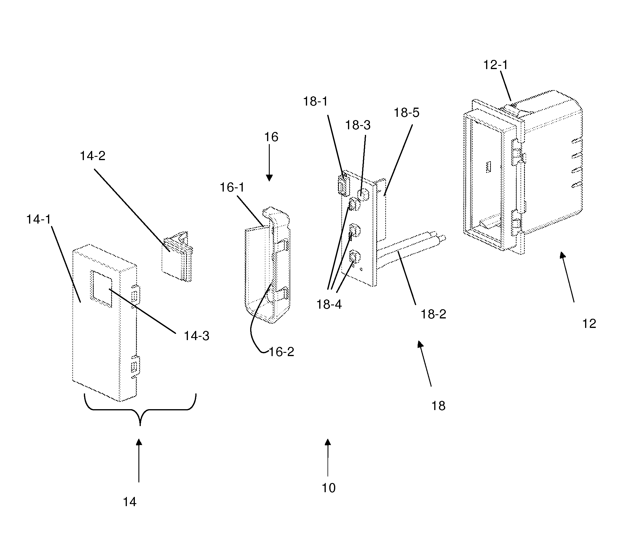
[0027]Reference will now be made in detail to the present exemplary embodiments of the invention, examples of which are illustrated in the accompanying drawings. Wherever possible, the same reference numbers will be used throughout the drawings to refer to the same or like parts. An exemplary embodiment of the switch of the present invention is shown in FIG. 4, and is designated generally throughout by reference numeral 100.

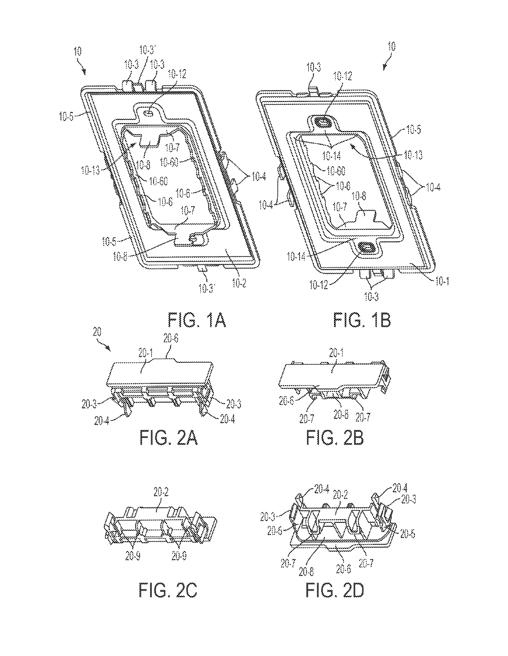
[0028]As embodied herein, and depicted in FIGS. 1A-1B, perspective views of a frame member 10 in accordance with the present invention are disclosed. FIG. 1A is directed to the rear side 10-2 of the frame member 10, whereas FIG. 1B is directed to the front side 10-1 of the frame member 10. The frame member 10 is configured to “complete the electrical enclosure” when one or more modular electrical devices (30, 40 or 50) and / or modular alignment connectors 20 are properly installed within the frame opening 10-13 such that the device wall box interior is substantial...


PUM


Abstract

The present invention is directed to an electrical device that includes a control circuit having a processing circuit, an electronic switch, light emitting elements and an ambient light sensor disposed on a substrate. The processing circuit provides an electronic barrier between the light emitting elements and the ambient light sensor such that the operation of the ambient light sensor is not contaminated by light emitted by the plurality of light emitting elements. A cover assembly includes a lens element and a switch actuator comprised of a diffusing material. The lens element and the switch actuator are disposed over the light emitting elements such that the light emitted by the light emitting elements is diffused by the lens element and the switch actuator to emit a substantially uniform illumination without any shadow or hot spot artifacts being visible on either the lens element or the switch actuator.

Description

CROSS-REFERENCE TO RELATED APPLICATIONS[0001]This is application is a continuation-in-part of U.S. patent application Ser. No. 13 / 680,675 filed on Nov. 19, 2012, the content of which is relied upon and incorporated herein by reference in its entirety, and the benefit of priority under 35 U.S.C. §120 is hereby claimed.BACKGROUND OF THE INVENTION[0002]1. Field of the Invention[0003]The present invention relates generally to electrical wiring devices, and particularly to electrical wiring devices with a night light.[0004]2. Technical Background[0005]The typical layout of a room, whether it is in a public space, a living space or a commercial space, provides a wall light switch disposed adjacent to the point of entry. In a scenario that most people are familiar with, a person crossing the threshold of a darkened room will usually attempt to locate the wall switch and turn the wall switch to the ON position before entering. Sometimes the wall switch is not located in this position and th...

Claims


Application Information

Patent Timeline
Patent Type & Authority Patents(United States)
IPC IPC(8): H01H9/02H01H23/00F21S8/02H01H19/04H01H13/04H02G3/12
CPCF21S8/024H01H23/00H02G3/12
Inventor TROLESE, LORENZOROHMER, RICHARD MFAI, LAM CHUNGCHUNG, LEUNG KWOKHAINES, JOSHUA
Owner PASS SEYMOUR
Why Eureka
Try Eureka