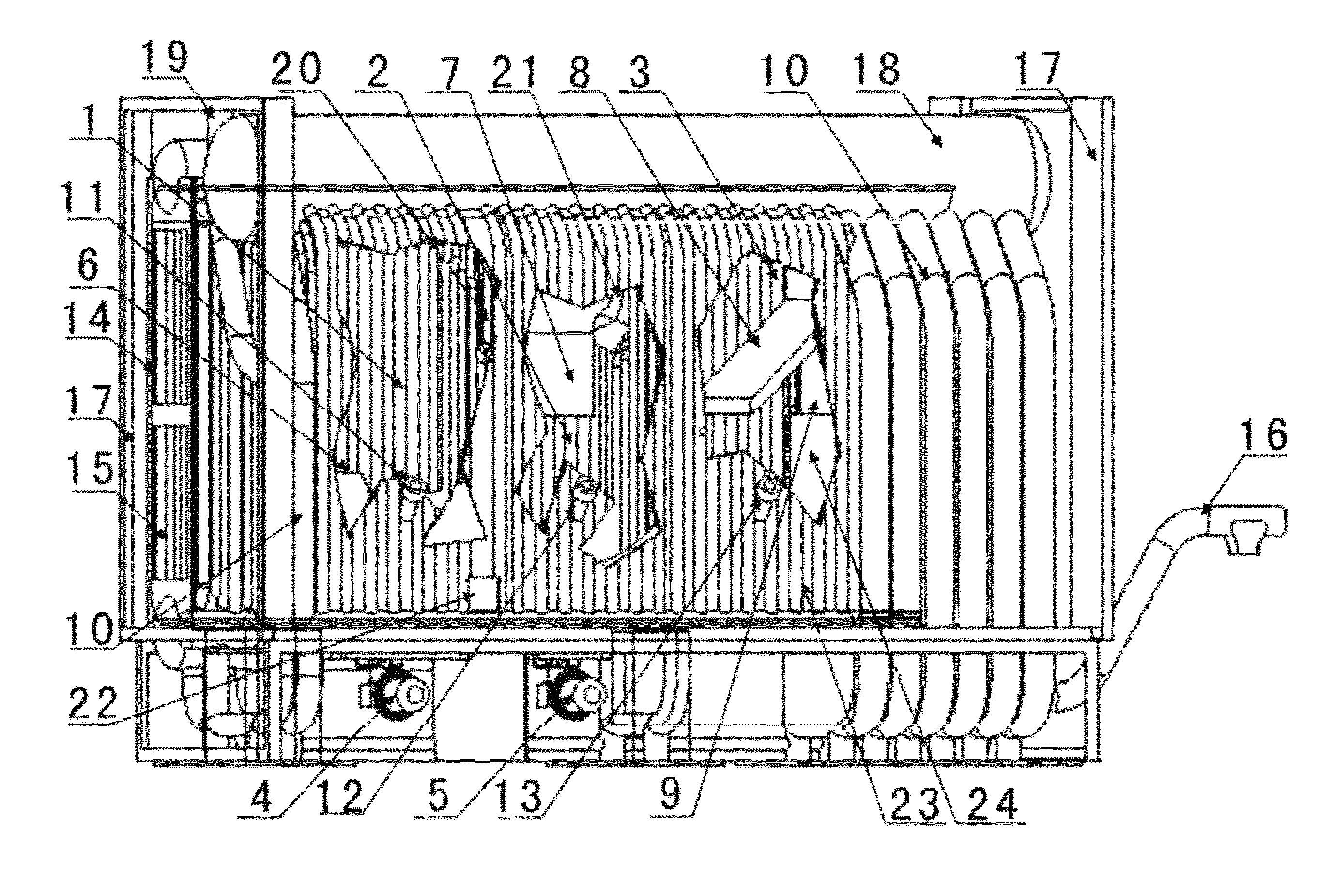
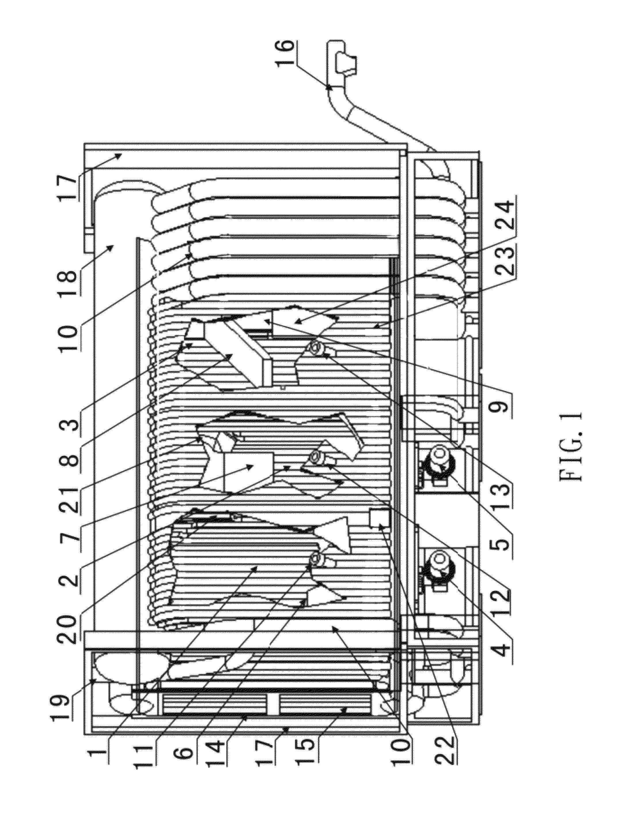
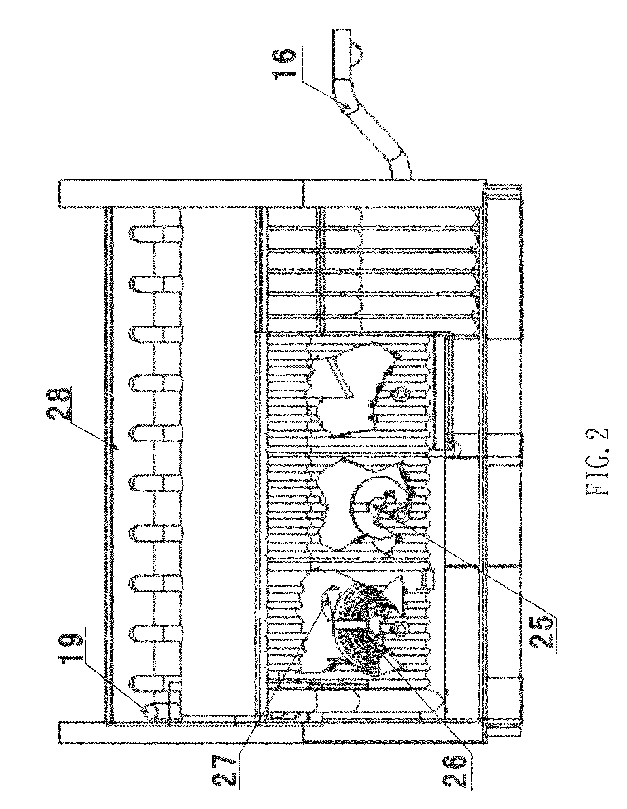
[0003]The object of the present invention is to provide a new type biomass fuel specific boiler, which can be controlled automatically, has a high combustion intensity, has a high burning-out rate, has a high thermal efficiency, has a small total volume with a small height, can run stably for a long time, and can use only the biomass fuel.
[0004]To achieve the above object, in view of the combustion characteristics of the biomass fuel, that is, it has a high content of fugitive constituent, the high temperature pyrolysis thereof is fast, it is prone to form ash shell and the ash has a low melting point, the present invention is made by adopting the mechanical fluidization technique, the hearth folding technique, the internal circulation technique, and the high temperature pre-dedusting technique in the integral design of the boiler. The technical solution of the present invention for solving the technical problem is: a new type biomass fuel internal circulation mechanical fluidized-bed corner tube intelligent boiler, comprising a primary combustion chamber, a primary combustion chamber Venturi tube internal circulator, a primary combustion chamber mechanical fluidizing machine, a secondary combustion chamber, a secondary combustion chamber profiled separator, a secondary combustion chamber mechanical fluidizing machine, a burning-out chamber, a high temperature multi-tube cyclone dust collector, a heat convection pipe bundle. The main points thereof are as follows: the primary combustion chamber adopts a square membrane water-cooled wall and a seat with a square top and a circular bottom to constitute a profiled hearth, at the bottom of the seat, there is mounted a primary combustion chamber mechanical fluidizing machine, the primary combustion chamber mechanical fluidizing machine fluidizing fin adopts a hollow wind protection structure, on the primary combustion chamber mechanical fluidizing machine air distributing plate, there is mounted an oriented blast cap, at the four corners of the seat, there are mounted Venturi tube internal circulators. Upon combustion, the biomass fuel enters the primary combustion chamber via the feed inlet. After the biomass fuel enters the primary combustion chamber, it quickly pyrolyzes and burns under the action of the high temperature environment. Under the collective action of the mechanical fluidizing fin, the oriented blast cap and the Venturi tube nozzle, the fuel exhibits fast rotary combustion. The primary air is provide by the oriented blast cap, the wind protection fluidizing fin and the Venturi tube. The wind protection fluidizing fin is capable of quickly breaking the ash shell of the burning fuel, so as to increase the combustion rate and prevent the slag formation through the bonding of the ash shell. The large carbon granules after the pyrolysis combustion of the fuel under the action of the cyclone are thrown to the four corners of the fire wall, and are trapped by the trap hole of the Venturi tube internal circulator so as to return to the bottom of the combustion chamber and continue the combustion. The small carbon granules and the hot fume after the combustion of the primary large carbon granules are discharged into the secondary combustion chamber via the fume outlet of the primary combustion chamber.
[0005]Said secondary combustion chamber consists of the secondary combustion chamber profiled separator and the secondary combustion chamber mechanical fluidizing machine. The secondary combustion chamber profiled separator consists of the secondary combustion chamber square membrane water-cooled wall, the secondary combustion chamber profiled seat with a square top and a circular bottom, and the secondary combustion chamber profiled fume-venting tube. The secondary combustion chamber mechanical fluidizing machine is mounted at the bottom of the secondary combustion chamber. After the hot fume which enters through the fume outlet of the primary combustion chamber is separated by the secondary combustion chamber profiled separator, the small carbon granules deposit on the bottom and the fluidization combustion continues. The secondary air is provided by the mechanical fluidizing machine wind protection fluidizing fin. The mechanical fluidization on the small carbon granules by the wind protection fluidizing fin may cause the secondary air and the fuel to sufficiently mix up so as to improve the combustion intensity and effectively prevent the slag formation through the bonding of the ash shell. The hot fume after the combustion of the secondary small carbon granules and a small amount of micro-carbon granules are discharged into the burning-out chamber via the profiled fume-venting tube of the secondary combustion chamber to subject to the tertiary burning-out combustion.
[0006]Said burning-out chamber consists of a membrane water-cooled wall which is internally coated with refractory concrete. In the middle of burning-out chamber, there is mounted a refractory concrete baffle plate, which causes perturbation on the fume so as to improve the tertiary combustion rate. The high temperature multi-tube cyclone dust collector is mounted at the rear portion of the burning-out chamber. The fume inlet of the high temperature multi-tube cyclone dust collector is connected with the burning-out chamber, and the fume outlet of the high temperature multi-tube cyclone dust collector is connected with the heat convection pipe bundle. The hot fume containing fine carbon granules which enters via the secondary combustion chamber subjects to the final tertiary burning-out combustion in the burning-out chamber. The perturbation of the refractory concrete baffle plate on the fume increases the contact of air with the fuel and also increases the tertiary combustion rate. The hot fume after the tertiary burning-out combustion firstly enters the high temperature cyclone dust collector for being dedusted, exchanges heat via the heat convection pipe bundle, and then is discharged out via the fume outlet of the boiler.
[0007]The present invention adopts the mechanical fluidization, and Venturi tube internal circulation combustion style and the sectional thermal burden may reach 6 MW / m2. The primary combustion chamber, the secondary combustion chamber and the burning-out chamber that are successively provided from the front to the rear in the boiler may keep the fuel in the fluidization, suspension firing condition throughout the three hearths by means of the design of the internal various structures. As a result, the height of the fluidized-bed boiler is effectively reduced, and the height of the hearth may be controlled to be about 2 meters. The pyrolysis and the primary circulation fluidization combustion of the coarse carbon granules in the primary combustion chamber, the separate secondary fluidization combustion of the fine carbon granules in the secondary combustion chamber and the tertiary suspension complete combustion in the burning-out chamber constitutes the precise sectional combustion system of the boiler, and the burning-out rate of the fuel may be up to above 99%. In particular, through the coating of the refractory concrete on the membrane water-cooled wall to adjust the amount of the heat exchange by radiation, the temperature of the primary combustion chamber may be controlled to be about 900° C., the temperature of the secondary combustion chamber may be controlled to be about 800° C., the temperature of the burning-out chamber may be controlled to be about 600° C., and the emission of NOx is effectively reduced. The high temperature multi-tube cyclone dust collector mounted at the rear portion of the burning-out chamber may remove about 90% of the ash of the fume. The pollution of the ash to the heat convection pipe bundle may be effectively reduced, so as to improve the total heat exchange efficiency of the boiler and the performance of long time stable running.


