Method and system for processing an image featuring multiple scales

a technology of image and scale, applied in the field of image processing, can solve the problems of aggravated problems and substantial loss of images

Inactive Publication Date: 2015-07-28
RAMOT AT TEL AVIV UNIV LTD
View PDF57 Cites 3 Cited by
  • Summary
  • Abstract
  • Description
  • Claims
  • Application Information

AI Technical Summary

Benefits of technology

[0032]According to some embodiments of the present invention the modulation function has higher values when the local contrast is low, and lower values when the local contrast is high.

Problems solved by technology

Typically, although at the time of image capture the acquired dynamic range is rather large, a substantial portion of it is lost once the image is digitized, printed or displayed.
The problem is aggravated once the image is transferred to a display or a print medium which is often limited to about 50 levels per color-band.

Method used


Image

  • Method and system for processing an image featuring multiple scales
  • Method and system for processing an image featuring multiple scales
  • Method and system for processing an image featuring multiple scales

Examples


example 1

Thermal Images

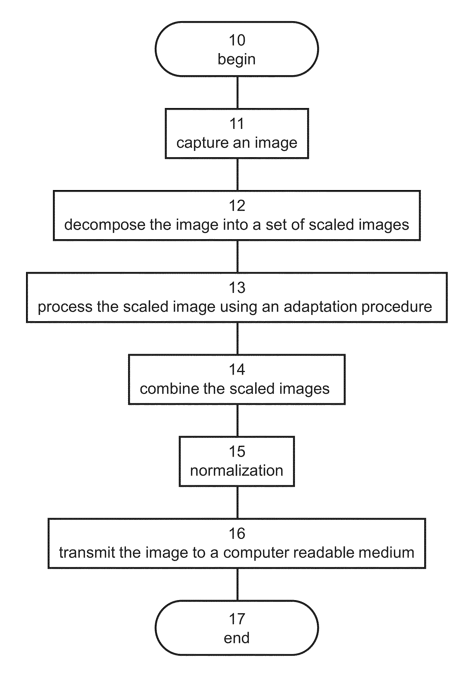
[0165]The technique of the present embodiments was employed to process thermal images acquired using an infrared camera. FIGS. 6A, 7A, 8A, 9A, 10A and 11A show the original images, before processing. Each image was processed according to some embodiments of the present invention as described in the flowchart of FIG. 1. The image was decomposed into 3 scaled images each of which was processed using EQs. 1, 2, 4, 5 and 7-14. The modulation coefficient was set to 1.

[0166]For the contrast-based adaptation procedure, up to six possible resolutions were employed. The application of the specific resolution was done such that the coarse resolution was applied to the overall scales for the whole image. In other word, fine resolution in the SORF were not included in the coarse general scales. Table 1 specifies the radii of the center and surround regions which were used for each resolution k.

[0167]

TABLE 1kradius of the center regionradius of the surround region113239351547125927...

example 2

HDR Images

[0169]Embodiments of the present invention were applied to High Dynamic Range images in an RGBE format. The original HDR images were obtained through the courtesy of Michael Werman, Erik Reinhard, Greg Ward, SpheronVR AG, Munsell Color Science Laboratory, and Paul Debevec's website.

[0170]Achromatic intensities were extracted from the polychromatic data of the images. This was performed by transforming each pixel in the RGBE image to CIE XYZ using the D65 sRGB transform matrix [IEC 61966-2-1:1999]. The achromatic intensity of each pixel was defined as the Y value of the pixel. Further transformation from the CIE XYZ space to CIE xyz was performed for each pixel, and the x,z, values were applied to the new achromatic intensities yielded according to various exemplary embodiments of the present invention.

[0171]Each image was processed according to some embodiments of the present invention as described in the flowchart of FIG. 1. The image was decomposed into 4 scaled images e...

example 3

Optimization Considerations

[0174]A multi-resolution representation of an image I, referred to below as “the artist” image was produced according to some embodiments of the present invention using a Reduce operation featuring Gaussian weights, thereby forming a Gaussian pyramid. The process was applied as follows:

Bn=Reduce(Bn−1),  (EQ. 16)

where the finest resolution B0 was set to be the original image:

B0=I.  (EQ. 17)

[0175]The obtained Gaussian pyramid for a set of six scaled images I0, . . . , I5 is shown in FIGS. 13A-F.

[0176]A relative luminance qn was then calculated according to the relation:

qn=In / In+1,  (EQ. 18)

where In is the nth scaled image and In+1 is an interpolated version of the n+1 scaled image obtained using the Expand operator:

In=Bn

In+1=Expand(Bn+1)  (EQ. 19)

[0177]The calculation of relative luminance resulted in a luminance pyramid corresponding to the relative luminance levels q0, . . . , q4, shown in FIGS. 14A-E.

[0178]Once the luminance pyramid was obtained, a local...


PUM


Abstract

A method of processing an image is disclosed. The method comprises obtaining an image decomposed into a set of scaled images, each being characterized by a different image-scale; and calculating, for each of at least some scaled images, a relative luminance between the scaled image and another scaled image of the set, using intensities in the scaled image and intensities in the another scaled image. The method further comprises processing each scaled image using an adaptation procedure featuring an image-specific effective saturation function of the relative luminance, thereby providing a processed scaled image; combining at least some of the processed scaled images to provide a combined image; and outputting the combined image to a computer readable medium.

Description

RELATED APPLICATIONS[0001]This application is a Continuation-in-Part of PCT Patent Application No. PCT / IL2011 / 000639 having International filing date of Aug. 4, 2011, which claims the benefit of priority under 35 USC §119(e) of U.S. Provisional Patent Application No. 61 / 370,812 filed on Aug. 5, 2010. The contents of the above applications are all incorporated by reference as if fully set forth herein in their entirety.FIELD AND BACKGROUND OF THE INVENTION[0002]The present invention, in some embodiments thereof, relates to image processing. Specifically, the present embodiments can be used for providing an automatic dynamic range modulation of a digital image. In various exemplary embodiments of the invention the method and / or apparatus is used for companding (compressing and expanding) a high dynamic range (HDR) image. The present embodiments further comprise an imaging system.[0003]High dynamic range imaging (HDRI) is a set of techniques that allow a far greater dynamic range of ex...

Claims


Application Information

Patent Timeline
Patent Type & Authority Patents(United States)
IPC IPC(8): G06K9/00G06T9/00G06T5/50
CPCG06T9/00G06T5/50G06T2207/20016G06T2207/20208H04N23/741G06T3/40H04N5/265
Inventor BARKAN, YUVALSPITZER, HEDVAFALTIN GEFEN, YAEL
Owner RAMOT AT TEL AVIV UNIV LTD
Why Eureka
Try Eureka