
Powered apparatus for fluid applications

a technology for fluid applications and powered apparatuses, which is applied in the direction of computer control, process and machine control, instruments, etc., can solve the problems of requiring either inconvenient/inaccurate test strips or very expensive instrumentation meters, and other types of equipment for testing, monitoring and/or control are expensive to purchase and install, and require an external source of power

Active Publication Date: 2015-08-04
BREAU KENNETH WILLIAM +1
View PDF53 Cites 19 Cited by
  • Summary
  • Abstract
  • Description
  • Claims
  • Application Information

AI Technical Summary

Benefits of technology

This patent is about a powered device that can be used in a fluid conduit, such as a water feature. The device includes a housing, a generator, and a storage device all in one. It can also have a controller to manage power storage, wireless communication, and monitoring of fluid parameters. The device can be charged using a docking station. The technical effect of this invention is the ability to provide a powered device that can be easily installed in a fluid conduit and used for various applications like lighting, monitoring, and pumps.

Problems solved by technology

Typically water feature illumination devices are manufactured and sold in a form that requires an external electrical power source with very expensive purchasing / installation costs.
Water testing and monitoring has been a problem requiring either inconvenient / inaccurate test strips or very expensive instrumentation meters.
Other types of equipment for testing, monitoring and / or control are expensive to purchase and install and require an external source of power.

Method used


Image

  • Powered apparatus for fluid applications
  • Powered apparatus for fluid applications
  • Powered apparatus for fluid applications

Examples


Embodiment Construction

[0019]For the purposes of promoting an understanding of the principles of the invention, reference will now be made to preferred embodiments and specific language will be used to describe the same. It will nevertheless be understood that no limitation of the scope of the invention is thereby intended, such alterations and further modifications in the described apparatus, and such further applications of the principles of the invention as illustrated therein being contemplated as would normally occur to one skilled in the art to which the invention relates.

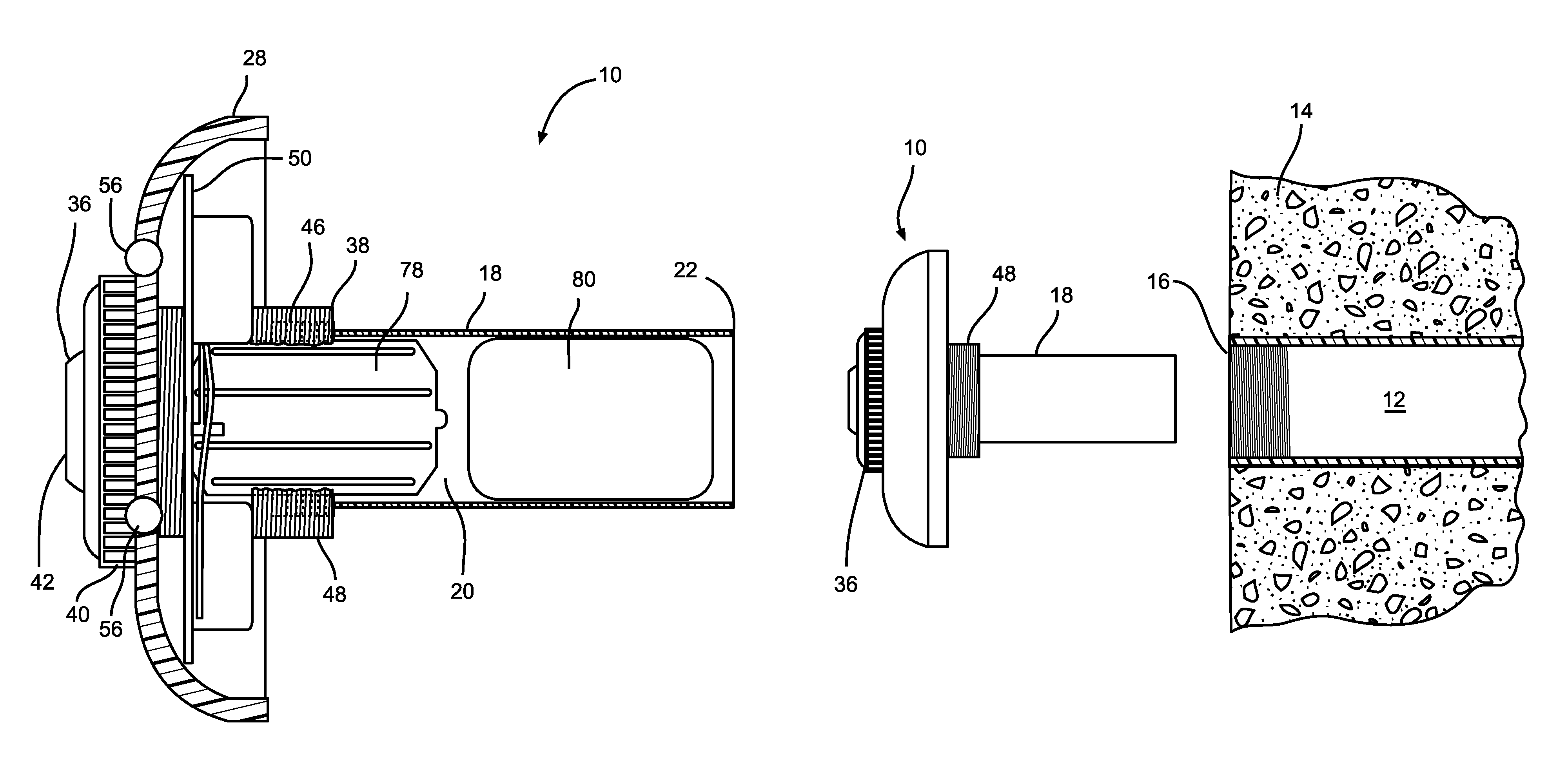
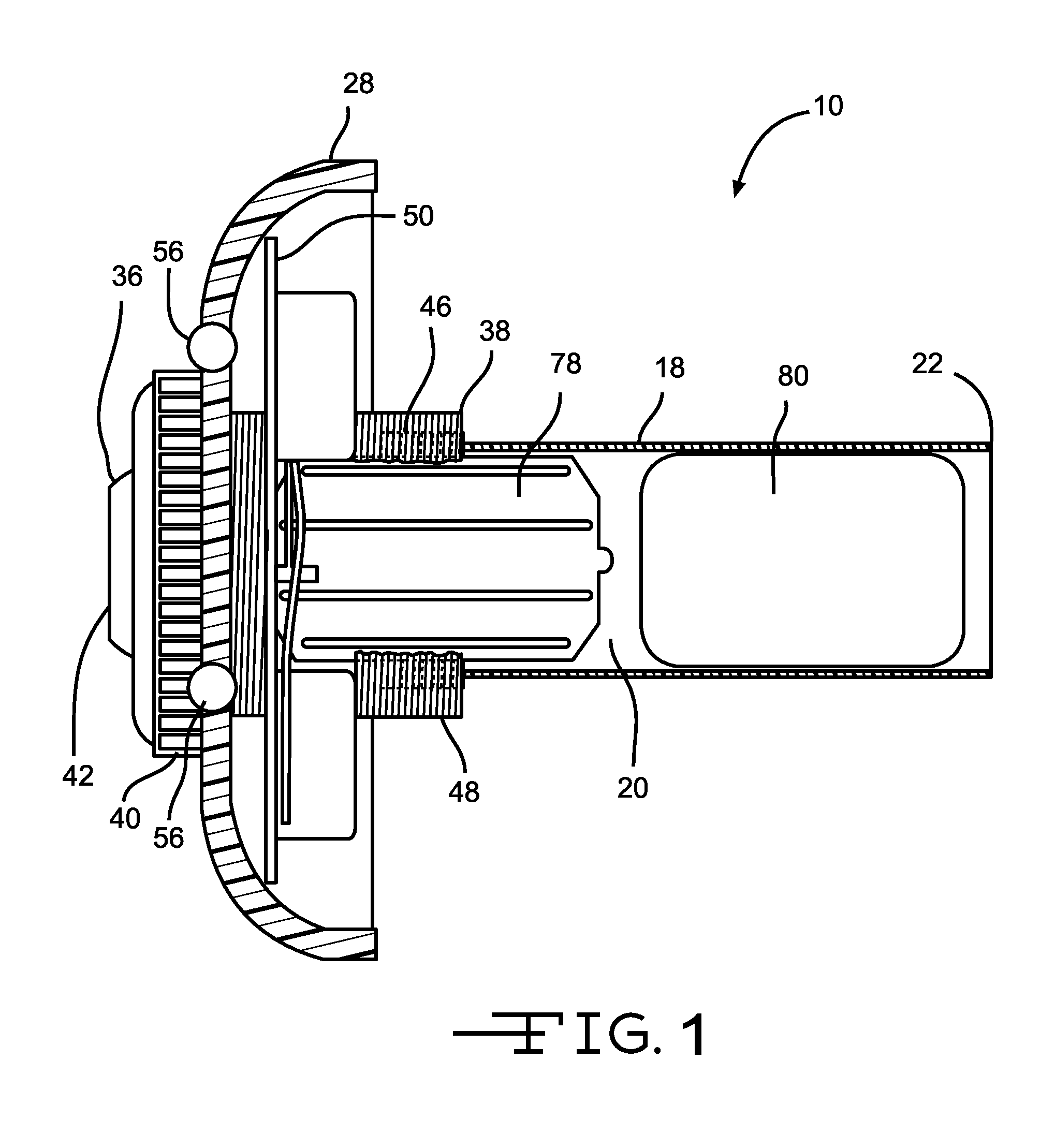
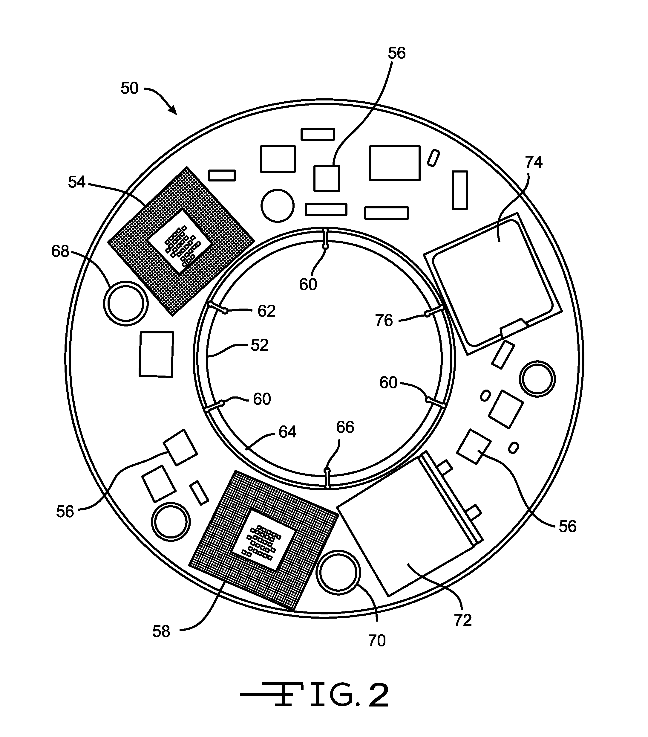
[0020]The present invention relates to a powered apparatus for a fluid application. The fluid application can be any application in which fluid flows through a conduit, by which is meant any channel, pipe, tube, line, opening, orifice, or the like through which fluid flows. For example, the fluid application can be any commercial, household (residential), industrial or public fluid application. The fluid can be practically any type...


PUM


Abstract

A powered apparatus for fluid applications includes a housing dimensioned and configured for mounting in a fluid conduit. The apparatus includes a generator for generating power. The apparatus also includes a power storage device for storing the generated power. The housing, generator and storage device comprise an integrated unit. The apparatus also includes a device connected to be powered by the generated power, for example, LED or OLED lighting. In certain embodiments, the apparatus can be mounted in a fluid conduit of a water feature. In another embodiment, the apparatus includes a microprocessor for controlling at least one of power storage, wireless communication, and monitoring of a parameter associated with the fluid. In another embodiment, the apparatus includes a controller and a power storage device and does not include a generator. The apparatus may further include a docking station for charging the power storage device.

Description

CROSS-REFERENCE TO RELATED APPLICATIONS[0001]This application claims the benefit of U.S. Provisional Application No. 61 / 583,400, filed Jan. 5, 2012, and of U.S. Provisional Application No. 61 / 722,365, filed Nov. 5, 2012, the disclosures of which are incorporated herein by reference.BACKGROUND OF THE INVENTION[0002]This invention relates in general to powered apparatuses for fluid applications, and in particular to powered apparatuses for applications such as water features, irrigation systems, plumbing systems and others.[0003]It is common to include water features on properties for recreational or decorative purposes. For example, pools, spas and hot tubs are very popular for recreation and entertainment. Landscapers often use water features such as fountains, pools, ponds, cascades, waterfalls or streams to improve the decorative or aesthetic aspects of properties.[0004]The water features often include powered devices for improving their appearance or usefulness, or related to the...

Claims


Application Information

Patent Timeline
Patent Type & Authority Patents(United States)
IPC IPC(8): B05B1/14F03B13/10F03B13/00H04W4/80
CPCF03B13/10F03B13/00F05B2220/60Y02B10/50H04W4/80Y02E10/20H05B47/10H05B47/19E04H4/14E04H4/169A61H33/005G05B15/02G05D7/0629
Inventor BREAU, KENNETH WILLIAMWASON, ALAN GRIER
Owner BREAU KENNETH WILLIAM
Learn More