
Measuring system in a fluid circuit of a continuous inkjet printer, related fluid circuit and block designed to implement said measuring system

a technology of measuring system and fluid circuit, which is applied in printing, other printing apparatus, etc., can solve the problems of system remains, cost, and inability to use detectors in insulating fluids, and require the implementation of a significant number of components

Inactive Publication Date: 2015-08-11
MARKEM IMAJE HLDG
View PDF32 Cites 26 Cited by
  • Summary
  • Abstract
  • Description
  • Claims
  • Application Information

AI Technical Summary

Benefits of technology

[0070]The circuit can also comprise a removable ink cartridge adapted to fill the first tank by forced hydraulic communication. The pump for emptying the second tank toward the first tank is then advantageously the pump which makes it possible to fill the first tank by forced hydraulic communication from the removable ink cartridge.
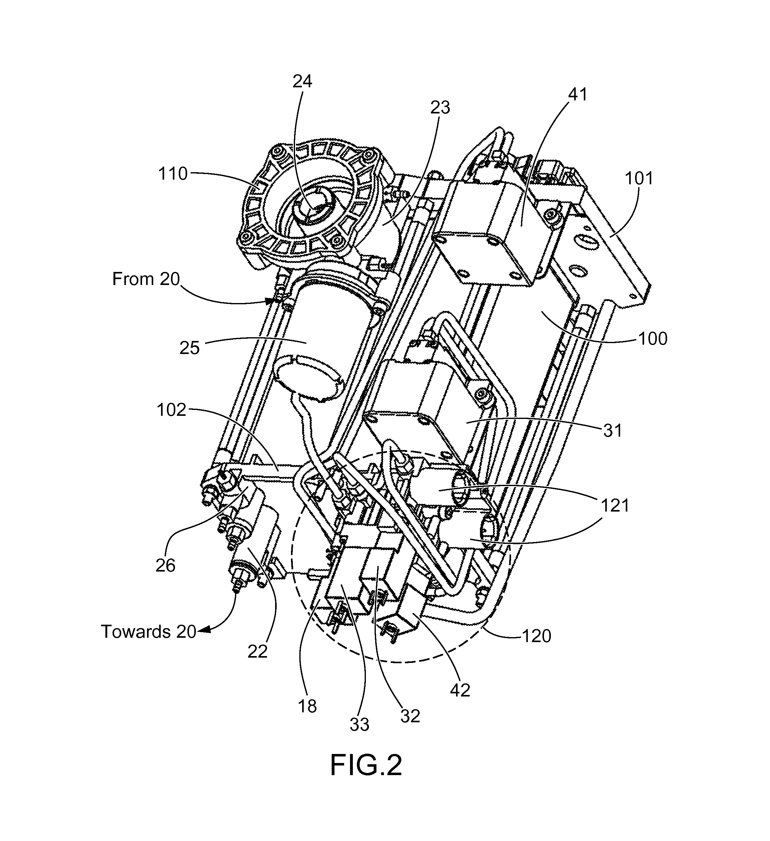
[0076]One thus defines a mechanical assembly for implementing all of the basic and utility functions which is compact, and simple and less expensive to manufacture and assemble.

Problems solved by technology

This system remains, however, costly due to the electronic protections which the standards require be implemented when electrical currents pass in flammable environments, which is in general the case of ink with volatile solvent.
Furthermore, this type of detector cannot be used with insulating fluids as solvents generally are.
These devices require the implementation of a significant number of components.
This method does not provide all of the desired flexibility in all situations, in particular due to the need to have an operational ink jet, i.e. effectively ejected by the head at a speed close to the nominal speed, to perform the measurement.
The major drawback of the solutions used by the prior art is that the quantity of solvent making it possible to correct a viscosity gap of the volume of ink contained in the intermediate tank can only be crudely evaluated since, on one hand, the concerned volume of ink is not precisely known, and on the other hand the volume of solvent added is also not precisely known.
This is due to the fact that the means used do not allow it (time for passage of a poorly-defined flow of solvent through a distribution member: solenoid valve or pump).
An approximate control of the viscosity in relation to the expected viscosity is of little consequence when robust inks are used but limits the possibilities for using the printer with sensitive inks.
However, the number of components and associated control interfaces, the difficulty of assembly and the resulting bulkiness of the system lead to prohibitive production costs and a non-optimal commercial situation.
2 / a category using the elements of the preceding category but with a decreased number of components, to the detriment of the performance of the printer or the service provided to the user.
These printers cannot be proposed for demanding applications.
The major drawback is that the evaluation is approximate, which makes it necessary to signal empty tanks (to be changed) with a sufficient safety margin, in order to avoid the ingestion of air by the head, well before the tanks are completely empty.
This results either in losing a large quantity of consumable, or requiring the user to visually monitor the level of the tanks, which is not practical.
Moreover, the absence of an intermediate tank leads to stopping printing during the changing of the removable tanks in order to avoid ingesting air, which would lead to triggering time-consuming maintenance operations.
This makes it possible to use fewer components and ensure greater compactness of the fluid circuit, but at the cost of significant complexity and a delicate reliability to master.
The different functions are managed sequentially (in series); this efficient system is still, however, particularly complex to develop due to the critical aspect of the timings between the phase of the variable volume cycle and the control of the solenoid valves.
This is complicated by the need to manage the response time of the different actuators of the system.
The large number of solenoid valves poses a reliability problem which requires technically high performances.
In the end, the drawbacks of the continuous inkjet printer ink circuits of the prior art according to their design can be summarized as follows:ink circuits in which each function is performed independently of the other functions: they consist of an assembly of simple solutions, but use many components to be integrated and controlled, which leads to a bulky and costly assembly;circuits with a sophisticated design to decrease the number of components (cost), but the complexity and reliability-related risk increases, by adding the development difficulty.
The need to develop non-standard hydraulic components impacts the cost-effectiveness of the final product;ink circuits with a very simplified architecture in order to obtain a low cost, but the technical and functional compromises lead to poor performance or decreased performance offered to the user and increased risk related to the feedback of insufficiently precise alarms.

Method used


Image

  • Measuring system in a fluid circuit of a continuous inkjet printer, related fluid circuit and block designed to implement said measuring system
  • Measuring system in a fluid circuit of a continuous inkjet printer, related fluid circuit and block designed to implement said measuring system
  • Measuring system in a fluid circuit of a continuous inkjet printer, related fluid circuit and block designed to implement said measuring system

Examples


Embodiment Construction

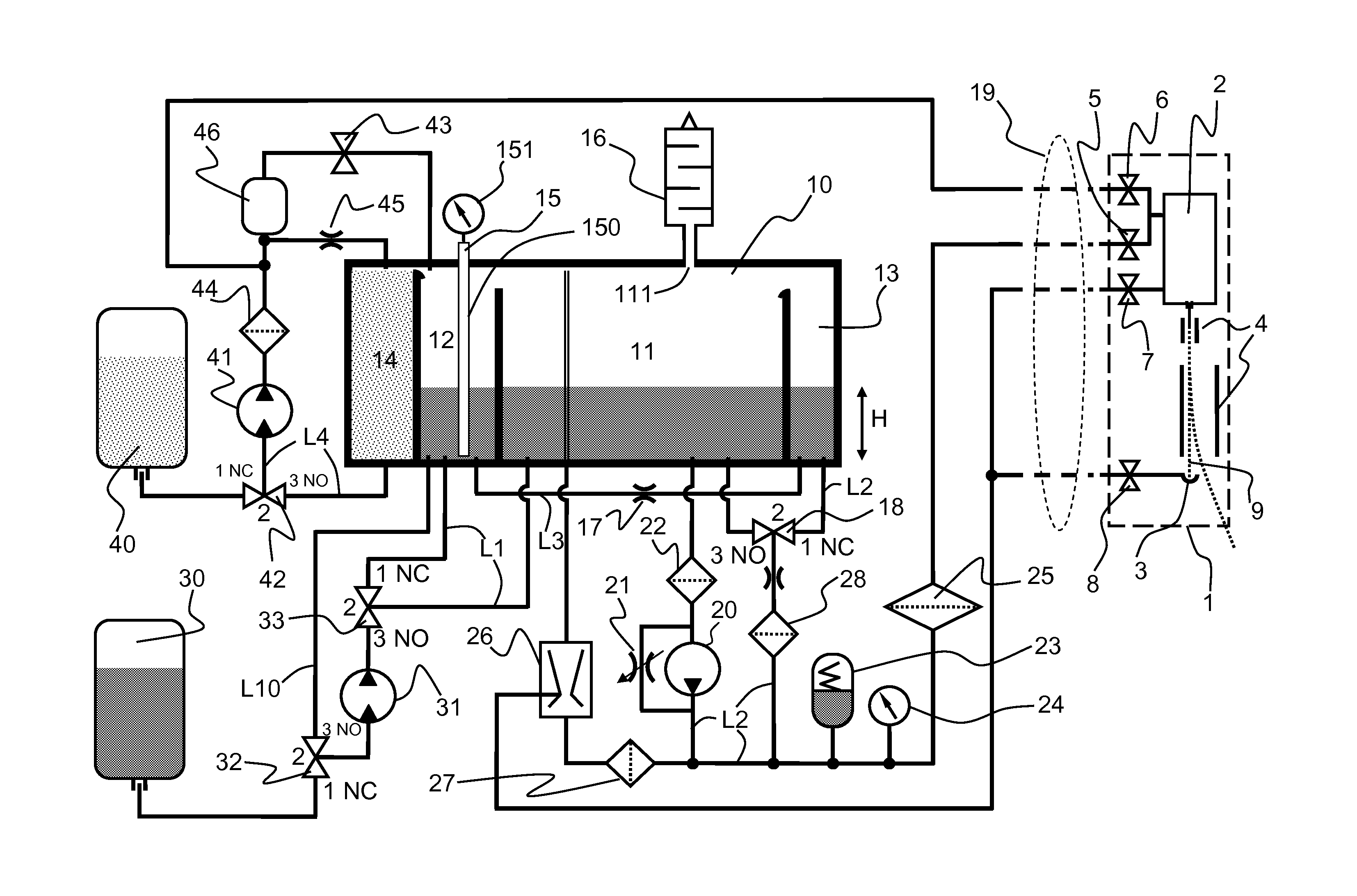
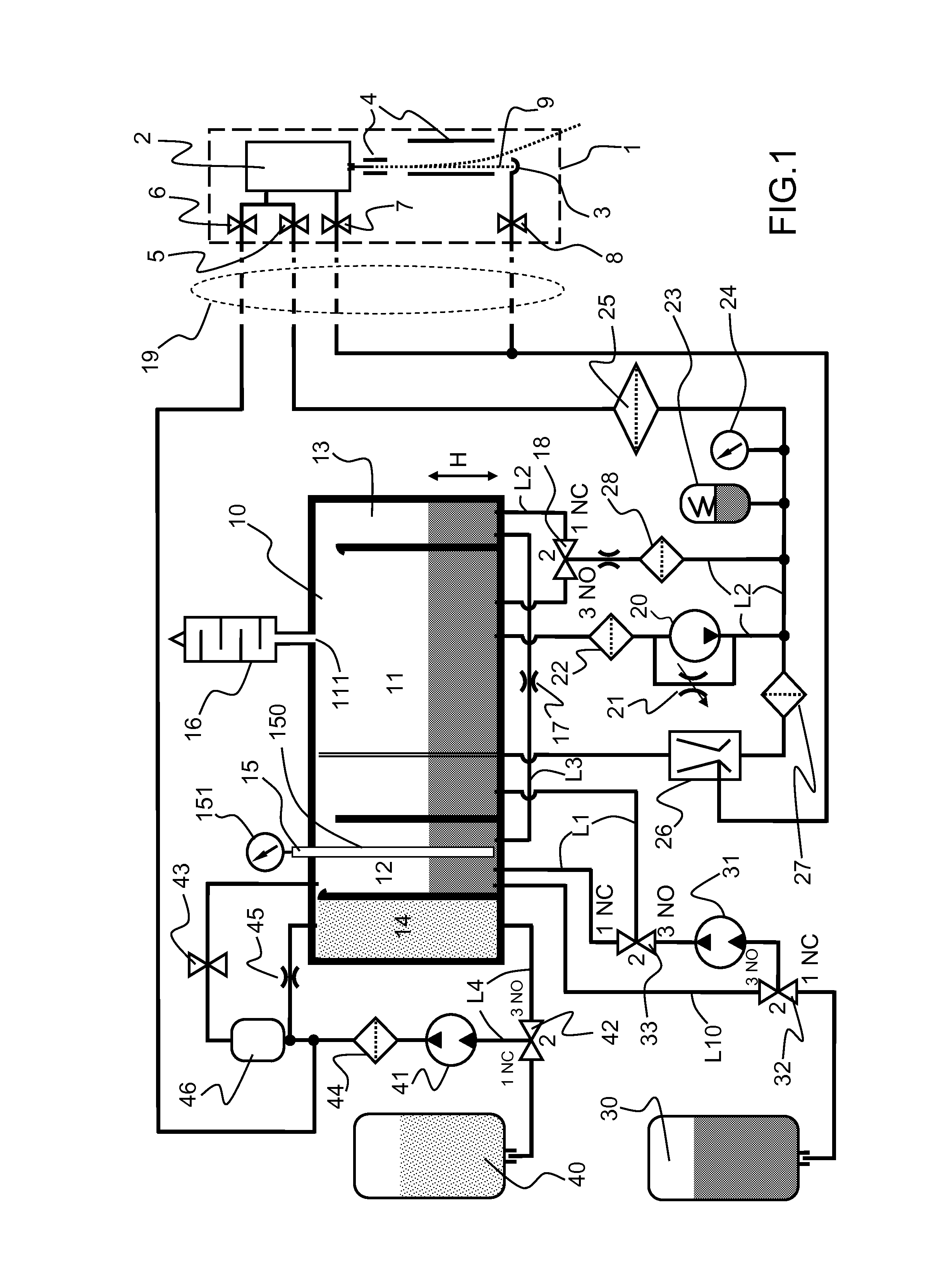
[0089]FIG. 1 shows a hydraulic diagram of the fluid circuit according to the invention, of a multi-deflected continuous inkjet printer with its printing head 1.

[0090]The head 1 comprises a drop generator 2 and a recovery gutter 3. It integrates four solenoid valves 5, 6, 7, 8 each connected to one of the four hydraulic conduits entering the head through the umbilical 19.

[0091]The ink-head solenoid valve 5 allows, in the open position, the supply of the drop generator 2 with pressurized ink.

[0092]The solvent-head solenoid valve 6 allows, in the open position, the supply of the drop generator 2 with pressurized solvent.

[0093]The purge solenoid valve 7 allows, in the open position, during certain maintenance operations, connection of the drop generator 2 to a vacuum source.

[0094]The gutter solenoid valve 8 allows, in the closed position, isolation of the gutter 3 when no jet 9 of ink is emitted by the drop generator. This prohibits air from entering when the jet 9 is not emitted in ord...


PUM


Abstract

The invention concerns a measuring system in a fluid circuit of a continuous inkjet printer. According to the invention, a system for measuring the quantity of ink is realized using a continuous sensor (15) equipping a measuring tank (12), which is first emptied then connected by communicating vessel with an intermediate tank (11) storing the ink which, pressurized, supplies the printing head and The measuring system advantageously constitutes a multifunctional system since it makes it possible, using a dedicated constant level tank (13) communicating with the intermediate tank (11) and also by communicating vessel with the measuring tank (12), to measure the viscosity of the ink and the correction thereof if necessary by adding solvent from a dedicated solvent tank (14).

Description

CROSS-REFERENCE TO RELATED APPLICATIONS[0001]This application is a U.S. national stage entry of International Application No. PCT / EP2010 / 070416 filed Dec. 21, 2010, which claims the benefit of U.S. Provisional Application No. 61 / 301,723 filed Feb. 5, 2010, and French Application No. 09 59504 filed Dec. 23, 2009, all of which are incorporated by reference herein in their entirety.TECHNICAL FIELD[0002]The invention concerns a measuring system in a fluid circuit in a continuous inkjet printer and more particularly a system making it possible to measure the quantity of ink and the viscosity of the ink as well as to correct this viscosity.[0003]It also concerns a fluid circuit of an inkjet printer, implementing such a measuring system which completes the two “basic” functions of the circuit, i.e. supplying the printing head with pressurized ink and recovering fluids returning from the head by suction.BACKGROUND OF THE INVENTION[0004]Continuous inkjet printers are well known in the field ...

Claims


Application Information

Patent Timeline
Patent Type & Authority Patents(United States)
IPC IPC(8): B41J29/38B41J2/175
CPCB41J2/175B41J2/17566B41J2/17596
Inventor PROTHON, FLORENTPOURTIER, FRANCISPOUZET, SEBASTIEN
Owner MARKEM IMAJE HLDG
Learn More