
Brake calipers

a brake caliper and caliper body technology, applied in the direction of axially engaging brakes, brake types, actuators, etc., can solve the problems of increased manufacturing and assembly complexity and/or costs, and easy damage to external pipes

Active Publication Date: 2020-04-14
LIBERTY VEHICLE TECH LTD
View PDF19 Cites 0 Cited by
  • Summary
  • Abstract
  • Description
  • Claims
  • Application Information

AI Technical Summary

Benefits of technology

The invention provides an improved brake caliper design that addresses issues in previous designs. It offers better stiffness, reduced weight, and is less prone to failure and expensive to manufacture and assemble. The channels within the caliper body are strategically located to enhance cooling efficiency and prevent vaporization of hydraulic fluid. The channel is connected to the caliper body or the limbs through a separable or fluidly connected pipe. The channel design encourages air to rise consistently and move towards the bleed port at the end of the hydraulic circuit. The external profile of the caliper is reduced, making it easier to package.

Problems solved by technology

The external pipe is susceptible to damage, leaks in the fluid connections and the use of additional components can increase manufacturing and assembly complexity and / or costs.
In use, the bridging portions at the ends of a caliper body can experience extremely high stresses and high temperatures, which can cause brake fluid to vaporise thereby resulting in brake failure.
The bridging portions must therefore be configured to mitigate such issues, which can require an increase in size, weight and / or complexity of the caliper body if the cross-over channel is to be incorporated in or in close proximity to such bridging portions.

Method used


Image

  • Brake calipers
  • Brake calipers
  • Brake calipers

Examples


Embodiment Construction

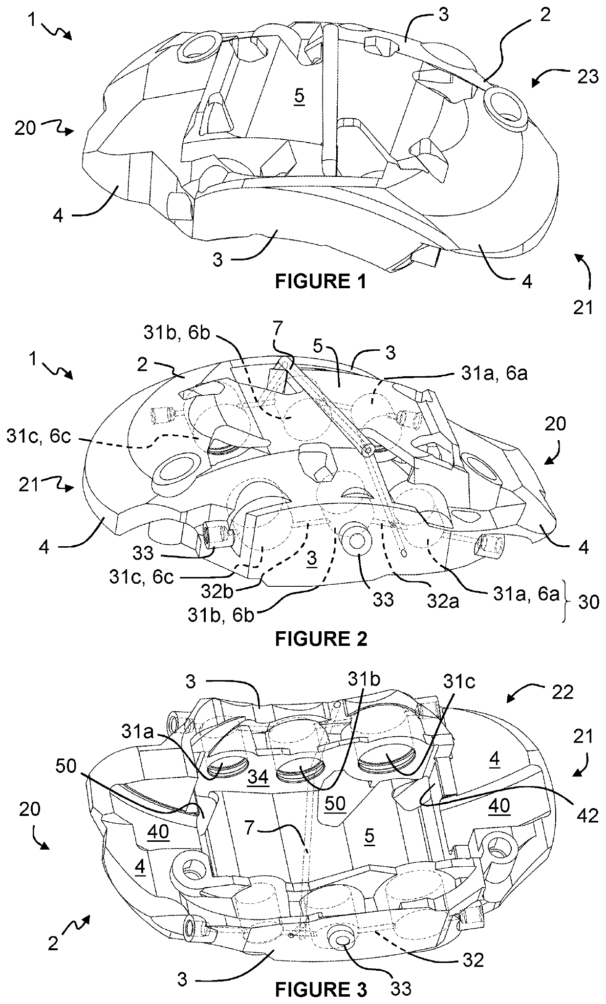
[0058]Referring to FIGS. 1 and 2, there is shown a brake caliper 1 including a caliper body 2 with a pair of spaced limbs 3, end bridging members 4, an intermediate bridging portion 5 and a series of actuating pistons 6a, 6b, 6c.

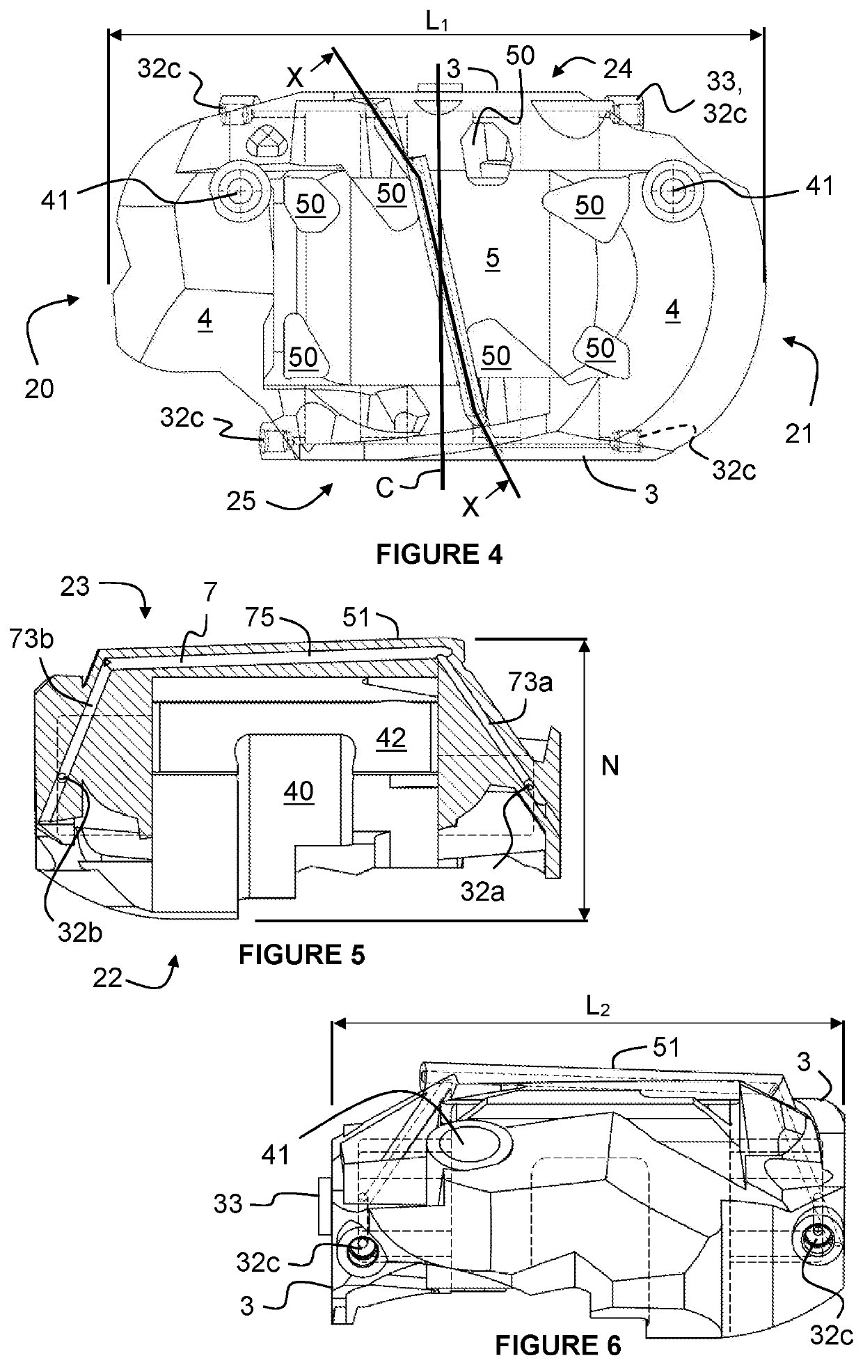
[0059]The caliper body 2, shown in FIGS. 1 to 6, includes a leading end 20, a trailing end 21, a brake disc receiving side 22, an outer side 23 opposite the brake disc receiving side 22, a mounting side 24 and a non-mounting side 25. The caliper body 2 also includes a longitudinal dimension L1 measured along a longitudinal direction from the leading end 20 to the trailing end 21, a lateral dimension L2 measured across the limbs 3 along a lateral direction orthogonal to the longitudinal dimension L1 and a normal dimension N or height measured along a normal direction orthogonal to both the longitudinal dimension L1 and the lateral dimension L2.

[0060]Each limb 3 includes a respective hydraulic circuit 30 including three hydraulic cylinders 31a, 31b, 31c withi...


PUM


Abstract

A brake caliper (1) including a caliper body (2) with a pair of spaced limbs (3), a pair of end bridging members (4) each joining together a respective end of each limb (3) and an intermediate bridging portion (5) between the bridging members (4) and joining together a respective intermediate portion of each limb (3). Each limb (3) includes a hydraulic circuit (30) including fluidly connected hydraulic cylinders (31a, 31b, 31c) within which respective pistons (6a, 6b, 6c) are received. The hydraulic circuits (30) are fluidly connected together by a fluid channel (7). Part of the fluid channel (7) is formed in the intermediate bridging portion (5) and extends diagonally across the space between the limbs (3) and between the bridging members (4).

Description

BACKGROUND1. Technical Field[0001]This invention relates generally to brake calipers for vehicles. More specifically, although not exclusively, this invention relates to a disc brake caliper body and to brake calipers, braking systems and vehicles incorporating such a brake caliper body.2. Related Art[0002]Conventional disc brake systems for vehicles include a disc coupled to the wheels, a brake caliper within which is received an outer segment of the disc and friction pads within the caliper on either side of the disc. The brake caliper includes one or more pistons reciprocable within a respective piston chamber that selectively compresses the disc between the pads to slow the vehicle.[0003]High performance disc brake systems often include one or more pistons on each opposing side of the disc for urging each of the brake pads toward the discs. In many such arrangements, pressurised brake fluid from the master cylinder is introduced at a single inlet and must be distributed to both ...

Claims


Application Information

Patent Timeline
Patent Type & Authority Patents(United States)
IPC IPC(8): F16D65/00F16D55/228F16D65/847F16D65/853F16D55/00F16D121/04
CPCF16D55/228F16D65/853F16D65/0068F16D65/847F16D2055/0016F16D2121/04
Inventor BLACKWELL, ANTHONYMUTCH-MATHIESON, DANIELPHILIPS, ANTHONYRIPPIN, LAURIESHEPHERD, BENJAMINTHOMAS, PHILIPYOUNG, STEVEN
Owner LIBERTY VEHICLE TECH LTD
Learn More