MR marker for magnetic resonance imaging

a magnetic resonance imaging and marker technology, applied in the direction of magnetic measurements, instruments, measurement devices, etc., can solve the problems of reducing the diagnostic value of the mr image produced, the convolution of the mr image, and the extension of the measurement tim

Inactive Publication Date: 2018-02-27
SIEMENS HEALTHCARE GMBH
View PDF5 Cites 0 Cited by
  • Summary
  • Abstract
  • Description
  • Claims
  • Application Information

AI Technical Summary

Benefits of technology

[0007]The object of the present embodiments is to specify an MR marker (e.g., an active MR marker) that at least reduces the problems addressed above. The MR marker is further intended to be useful for field correction methods or as a quasi invisible MR marker in MR imaging for finding the position of other devices or objects that are used or placed in a magnetic resonance imaging scanner (e.g., coils, intervention instruments, patient position).
[0012]Owing to the screening, the proposed MR marker is largely MR-invisible in MR imaging and permits inductive coupling of the RX field and / or the TX field of the magnetic resonance imaging scanner to the second marker coil. This second marker coil functions in one case as a receive coil for the TX field, and in the other case, as a transmit coil for coupling to the RX field. As a result, the technical design of the proposed MR marker is simpler, less susceptible to failure and, therefore, more reliable as compared with the known MR marker. The proposed MR marker may be used for field correction methods (e.g., B0 drift, eddy currents) or for detecting position in MR imaging. In one embodiment, the coupling between the MR marker and the magnetic resonance imaging scanner is performed explicitly inductively so that it is possible to dispense completely with a wired connection between the MR marker and magnetic resonance imaging scanner.
[0023]In the case of inductive RX and TX coupling of the second marker coil, it is possible to produce MR markers that may be used independently of a cable connection to the magnetic resonance imaging scanner. In order to receive the RX signal, the MR marker may be coupled inductively to an RX receive coil of the magnetic resonance imaging scanner in the case of specific parts of a pulse sequence of the magnetic resonance imaging scanner. Therefore, it is possible to provide a switch in the MR marker that may be operated automatically by an appropriate low-frequency switching signal. The omission of RF cable connections between MR marker and magnetic resonance imaging scanner is advantageous, since the connections are provided with surface wave filters, which are costly and space-consuming.

Problems solved by technology

However, the signals emitted by the marker medium are also received by the receive coil of the magnetic resonance imaging scanner for imaging (e.g., a body coil or local coil), and may lead to convolutions in the MR imaging.
The problems associated with the use of previously known MR markers reside in the fact that the MR markers produce MR signals and may therefore produce pixels outside an examination object during MR imaging.
This leads to extension of the measurement time, or a risk of convolutions that reduce the diagnostic value of the MR image produced, and thereby renders misdiagnosis possible through convolution of the marker signal.

Method used


Image

  • MR marker for magnetic resonance imaging
  • MR marker for magnetic resonance imaging
  • MR marker for magnetic resonance imaging

Examples


Embodiment Construction

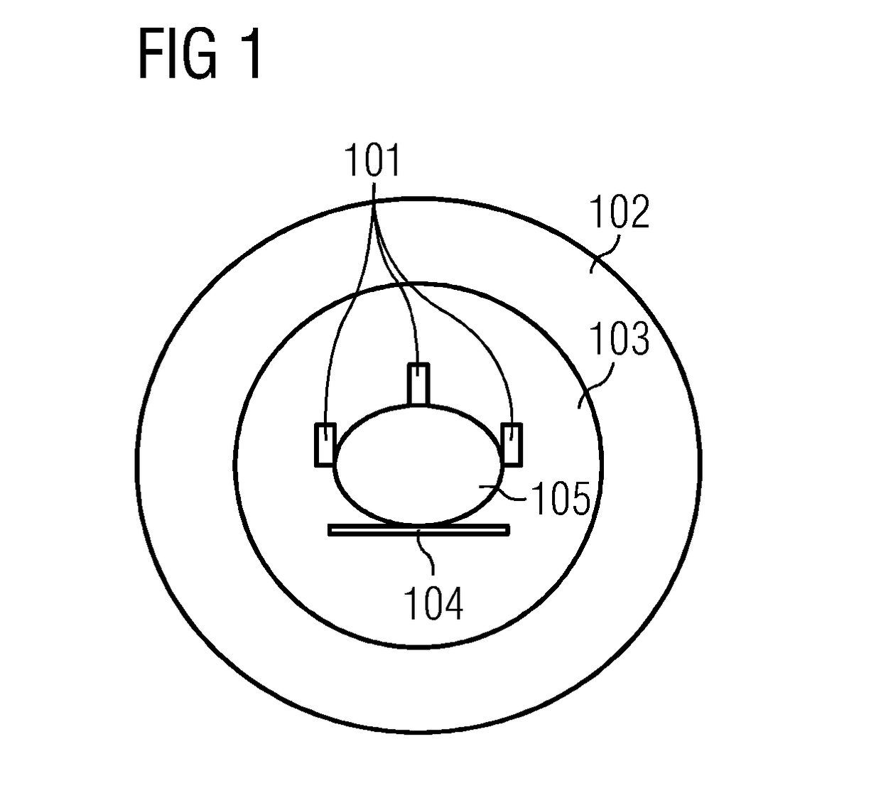
[0033]FIG. 1 depicts an embodiment of a schematic representation of a magnetic resonance imaging scanner 102 with a transmit / receive coil (e.g., body coil) 103, three MR markers 101 arranged on an examination object 105, and a patient table 104. The transmit / receive coil 103 serves here to emit a TX field and to receive an RX field in the magnetic resonance imaging scanner. Alternatively, or in addition, the TX field and the RX field may also be respectively emitted and received by a local coil. The TX field and the RX field have the Larmor frequency fLarmor of the particles (e.g., protons) respectively concerned. The TX field excites the particles in the examination object, and, at the same time, in the marker medium 201 of the three MR markers 101. The excited particles produce MR signals and thus a receivable RX field.

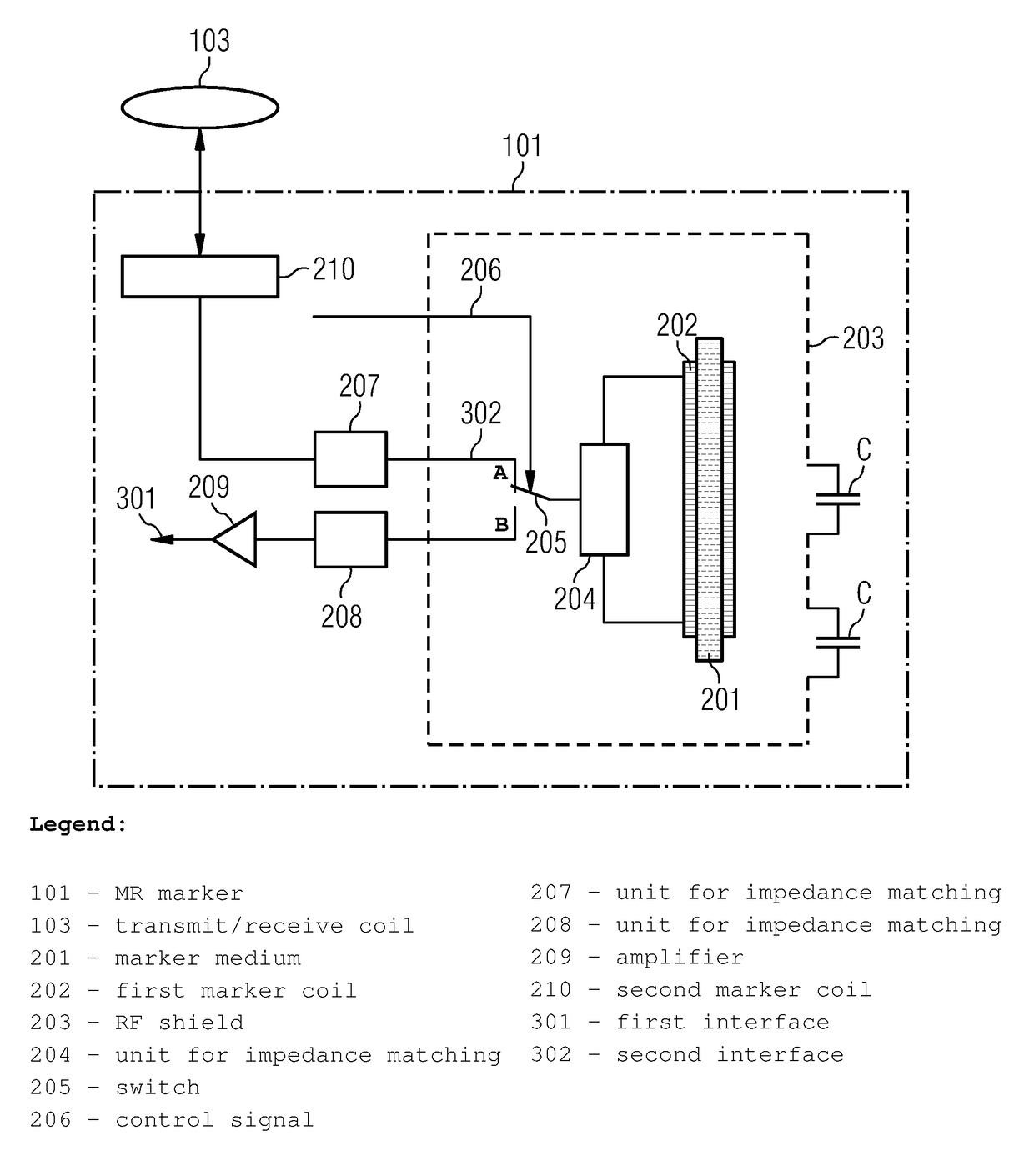
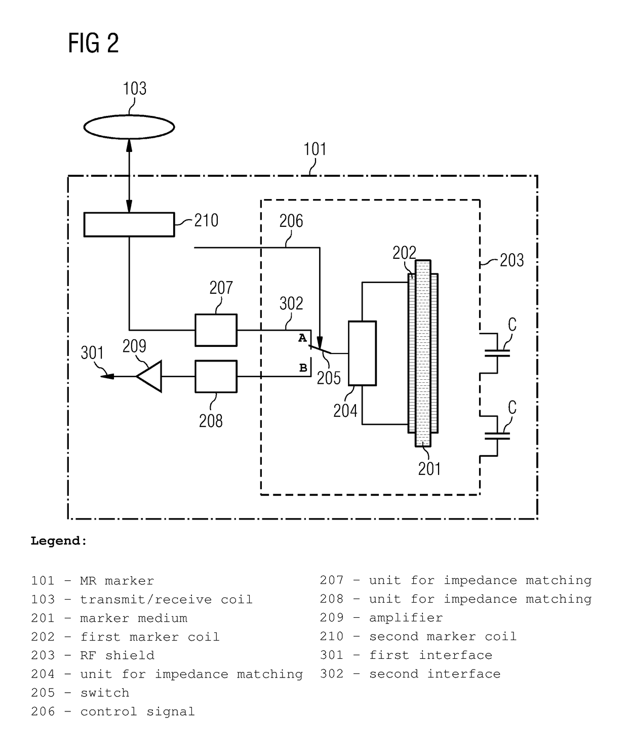
[0034]FIG. 2 depicts an embodiment of schematic setup of an MR marker 101. The MR marker 101 includes a closed volume, surrounded here by a glass tube containing a ...


PUM


Abstract

An MR marker for magnetic resonance imaging includes: (1) a closed volume containing a marker medium, (2) a first marker coil surrounding the volume for detecting an MR signal from the marker medium, (3) an RF shield which surrounds at least the volume and the first marker coil and screens against external RF fields, (4) a second marker coil, arranged outside the RF shield, for inductive and / or capacitive coupling to a magnetic field, and / or for emitting the MR signal detected by the first marker coil, (5) a first electrical interface for controllable electrical connection of the first marker coil to the magnetic resonance imaging scanner, (6) a second electrical interface for controllable coupling of the second marker coil and first marker coil, and (7) an electrical controller with which the first interface and / or the second interface may be controlled.

Description

CROSS-REFERENCE TO RELATED APPLICATIONS[0001]This application claims the benefit of DE 10 2013 215722.3, filed on Aug. 8, 2013, which is hereby incorporated by reference in its entirety.TECHNICAL FIELD[0002]The present embodiments relate to MR markers for magnetic resonance imaging. As used herein, “MR” refers to magnetic resonance imaging or nuclear magnetic resonance (NMR).BACKGROUND[0003]MR markers may be subdivided into passive and active MR markers. Passive markers may be detected in the MR image by their special contrast if they are situated in the imaging plane. The contrast is caused either by signal extinguishing (e.g., negative contrast) or signal amplification (e.g., positive contrast), as in the case of the inductively coupled coil. Signal extinctions are, for example, caused by susceptibility markers made from dysprosium oxide (Dy2O3). The susceptibility differences between the markers and the surrounding tissue lead to field gradients that cause a more rapid dephasing ...

Claims


Application Information

Patent Timeline
Patent Type & Authority Patents(United States)
IPC IPC(8): G01R33/34G01R33/58G01R33/36G01R33/422
CPCG01R33/34084G01R33/3642G01R33/58G01R33/3664G01R33/422G01R33/3692
Inventor BIBER, STEPHAN
Owner SIEMENS HEALTHCARE GMBH
Why Eureka
Try Eureka