
Canopy light system and associated methods

a canopy light and light system technology, applied in the field of canopies and light systems, can solve the problems of high material and component costs, high total cost of system components, and the complexity of current led-based linear illumination devices, and achieves the effects of less manufacturing and assembling costs, convenient and safe installation, and efficient heat dissipation

Active Publication Date: 2013-11-07
LIGHTING SCI GROUP
View PDF2 Cites 4 Cited by
  • Summary
  • Abstract
  • Description
  • Claims
  • Application Information

AI Technical Summary

Benefits of technology

The present invention is related to a low-profile LED canopy light system that can be used to retrofit a traditional canopy light. The system is advantageously cheaper, safer, and more efficient in heat dissipation than traditional retrofit solutions.

Problems solved by technology

However, a number of design challenges and costs are associated with replacing traditional lamps with LED illumination devices.
These design challenges include manufacturing cost control, installation ease, and thermal management.
While many approaches to driving LEDs are known in the art, the complex designs of current LED-based linear illumination devices often suffer from high material and component costs.
However, the requirement to employ multiple converters and regulators with each LED-based lighting device results in higher total cost for system components.
Replacement of legacy lighting solutions may be complicated by the need to adapt LED-based devices to meet legacy form standards.
For example, in a commercial lighting system retrofit, disposal of a replaced light's housing in a canopy structure often is impractical.
Because of such safety concerns, a design that uses high-voltage distribution wire may be less desirable than a design that employs low-voltage DC distribution wire.
However, the difficulty of quickly and safely installing new wiring without having to replace or cut pathways in existing structures, such as sheetrock or metal siding, leads current designers to instead reuse legacy wiring.
Another challenge inherent to operating LEDs is heat.
LEDs suffer damage and decreased performance when operating in high-heat environments.
Moreover, when operating in a confined environment, the heat generated by an LED and its attending circuitry itself can cause damage to the LED.
However, heat sinks can sometimes negatively impact the light distribution properties of the light fixture, resulting in non-uniform distribution of light about the fixture.
Heat sink designs also may add to the weight of an illumination device, thereby complicating installation, and also may limit available space for other components needed for delivering light.
However, reliance on oppositely directed pivot members to mechanically support the planar panel when installed limits the size of canopy fixture housings to which the retrofit may be applied.
Also, the depth of the electrical control elements presumes recessed mounting within an existing canopy fixture, thereby precluding low-profile flush-mounting applications.
However, including an expensive on-board power control unit for conversion and conditioning of power sacrifices manufacturing cost for the sake of installation ease.
Also, construction and assembly of the many separate components listed above adds to design complexity and cost for the disclosed canopy luminaire.
Addition of power supply units not only add manufacturing cost to the retrofit kit, but also limits installation ease by requiring space for a power supply unit to extend through a canopy and into a legacy fixture (as in the Fischer disclosure).

Method used


Image

  • Canopy light system and associated methods
  • Canopy light system and associated methods
  • Canopy light system and associated methods

Examples


Embodiment Construction

[0030]The present invention will now be described fully hereinafter with reference to the accompanying drawings, in which preferred embodiments of the invention are shown. This invention may, however, be embodied in many different forms and should not be construed as limited to the embodiments set forth herein. Rather, these embodiments are provided so that this disclosure will be thorough and complete, and will fully convey the scope of the invention to those skilled in the art. Those of ordinary skill in the art will realize that the following embodiments of the present invention are only illustrative and are not intended to be limiting in any way. Other embodiments of the present invention will readily suggest themselves to such skilled persons having the benefit of this disclosure.

[0031]Although the following detailed description contains many specifics for the purposes of illustration, anyone of ordinary skill in the art will appreciate that many variations and alterations to t...


PUM


Abstract

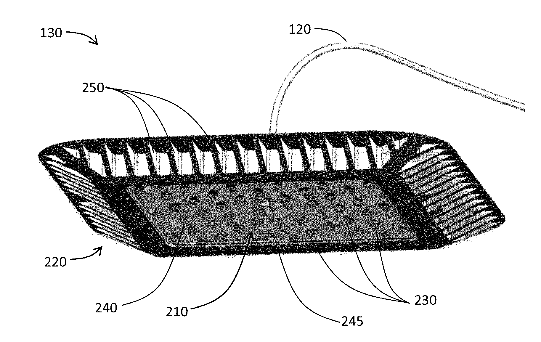
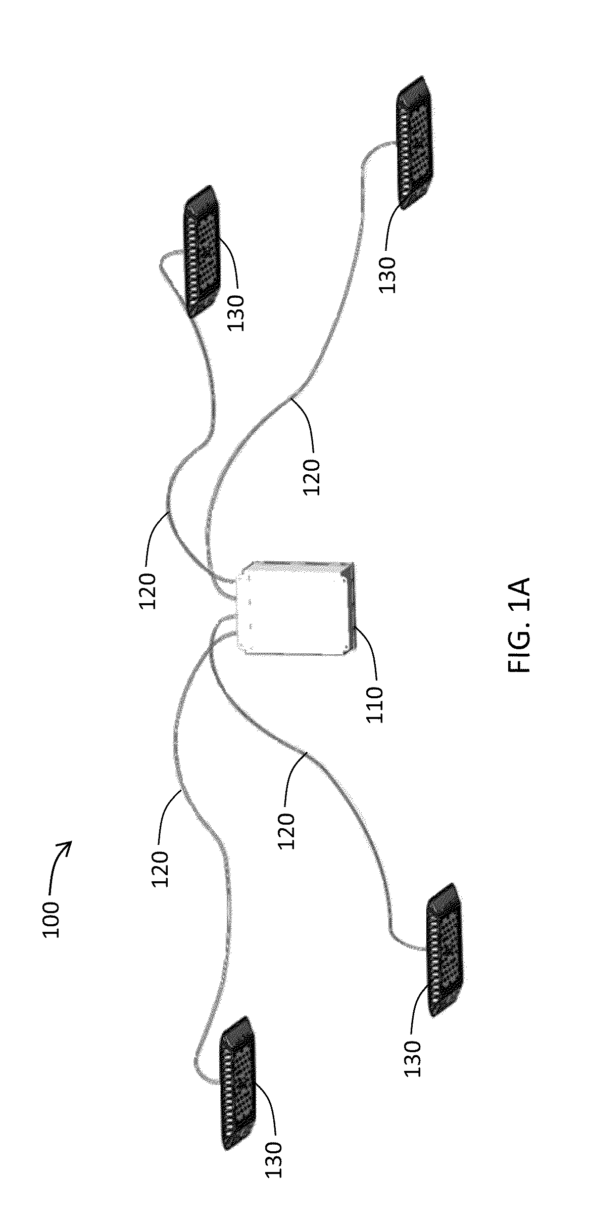
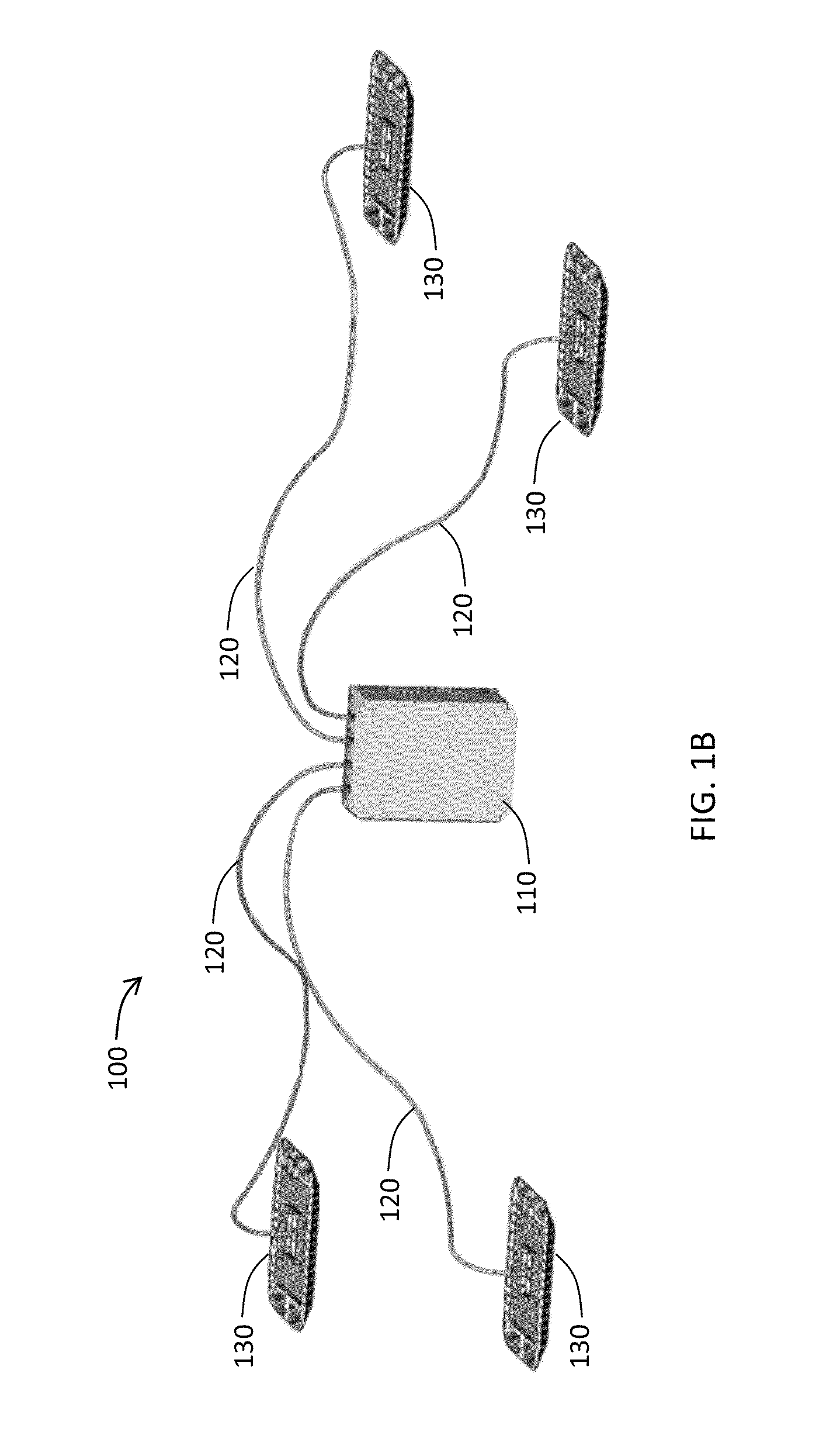
A retrofit canopy light system is provided that has a multi-output power supply assembly in electrical communication with a plurality of luminaire assemblies through a plurality of distribution wires. In one embodiment, each luminaire assembly may receive an electric current from a respective distribution wire extending from the power supply assembly. The power supply assembly may convert high-voltage AC to low-voltage, regulated DC. Each luminaire assembly may comprise a light source and a low profile, heat-dissipating frame in thermal and mechanical communication with the light source. The heat-dissipating frame may be constructed of a thermally conductive material, and may include a plurality of heat sink fins and bars. The heat-dissipating frame may present a substantially flat surface configured for flush mounting adjacent to an existing canopy fixture.

Description

RELATED APPLICATIONS[0001]This application claims the benefit under 35 U.S.C. §119(e) of U.S. Provisional Patent Application Ser. No. 61 / 643,302 filed on May 6, 2012 and titled Canopy Light System and Associated Methods, the entire contents of which are incorporated herein by reference.FIELD OF THE INVENTION[0002]The present invention relates to the field of illumination systems and, more specifically, to the field of illumination systems used in canopy lighting applications, and associated methods.BACKGROUND OF THE INVENTION[0003]Canopy lights are commonly used in outdoor service areas of fuel stations and convenience stores. Lighted canopies provide shelter, visibility, and security for consumers, as well as inviting storefronts that increase consumer traffic for businesses.[0004]As applied to canopy lighting systems, digital lighting technologies such as light-emitting diodes (LEDs) offer significant advantages over legacy light sources such as incandescent, high-intensity discha...

Claims


Application Information

Patent Timeline
Patent Type & Authority Applications(United States)
IPC IPC(8): F21V15/01F21V23/00
CPCF21V15/011F21V23/009F21V23/008F21V29/507F21V29/77F21Y2115/10F21S8/04F21V15/01F21V19/003F21V23/001F21V23/02F21V23/06
Inventor MAXIK, FREDRIC S.BARTINE, DAVID E.SCHELLACK, JAMES LYNNWIDJAJA, ADDY S.
Owner LIGHTING SCI GROUP
Learn More