Method and apparatus of wide-angle optical beamsteering from a nanoantenna phased array

a phased array, nanoantenna technology, applied in the direction of optics, optical elements, instruments, etc., can solve the problem of difficult to achieve desirable spacing

Active Publication Date: 2015-08-11
NAT TECH & ENG SOLUTIONS OF SANDIA LLC
View PDF1 Cites 45 Cited by
  • Summary
  • Abstract
  • Description
  • Claims
  • Application Information

AI Technical Summary

Benefits of technology

The patent describes a way to control the phase of light emitted from a one-dimensional array of emitters. By controlling the phase of each emitter, the emissive plane of the array can be steered. Multiple parallel arrays can be used to provide steering in two dimensions. This method eliminates the need for individual phase-shift elements, allowing for smaller antenna spacings and potentially greater beam steering. The resulting beam also has the advantage of being free from random noise typically seen when individual emitters are phase-biased.

Problems solved by technology

The technical problem addressed in this patent text is the need for additional approaches to optical beam steering that provide both a wide frequency-tuning range and a wide two-dimensional scan range in a chip-scale device.

Method used


Image

  • Method and apparatus of wide-angle optical beamsteering from a nanoantenna phased array
  • Method and apparatus of wide-angle optical beamsteering from a nanoantenna phased array
  • Method and apparatus of wide-angle optical beamsteering from a nanoantenna phased array

Examples


example numerical

Simulation

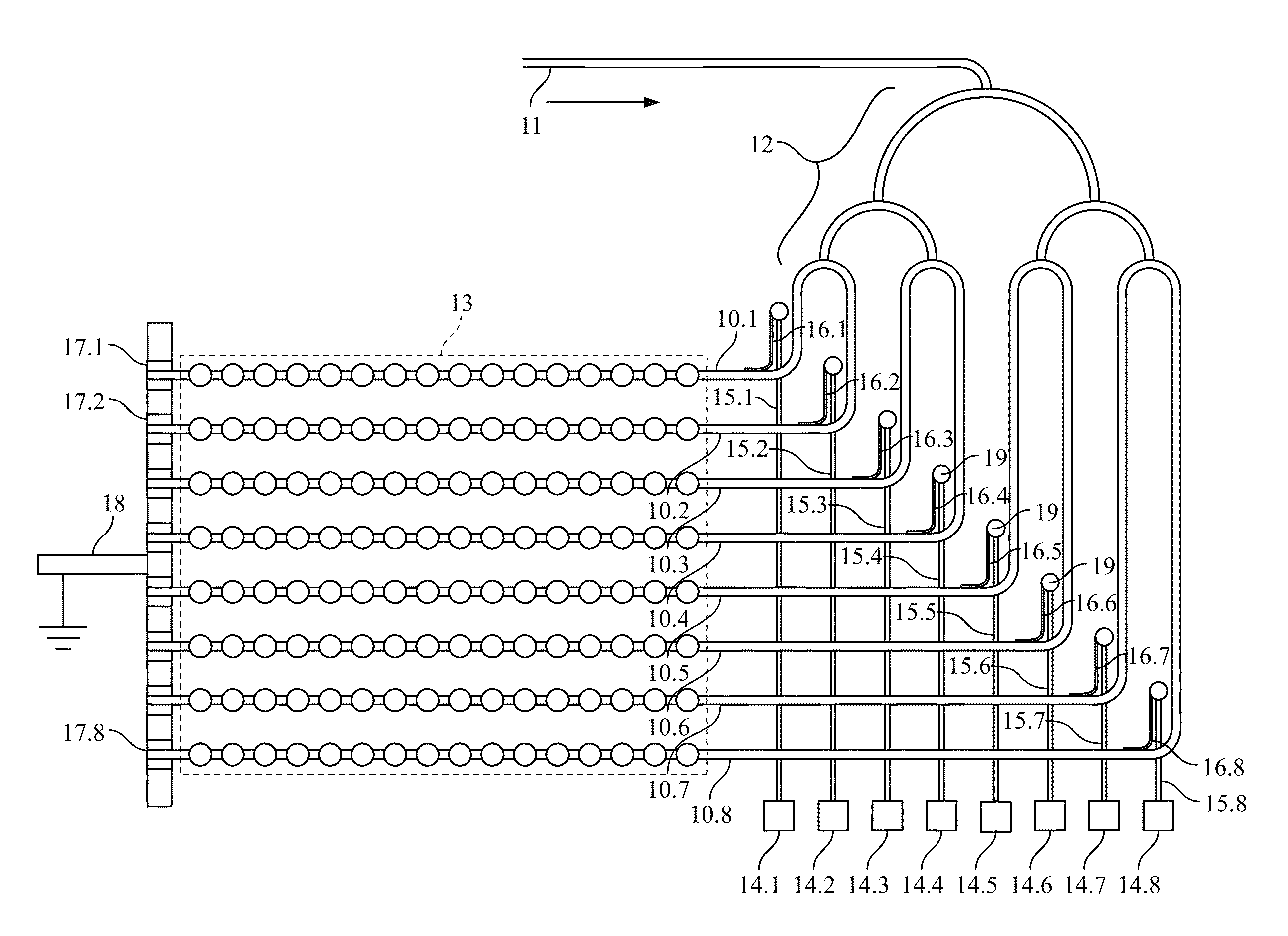
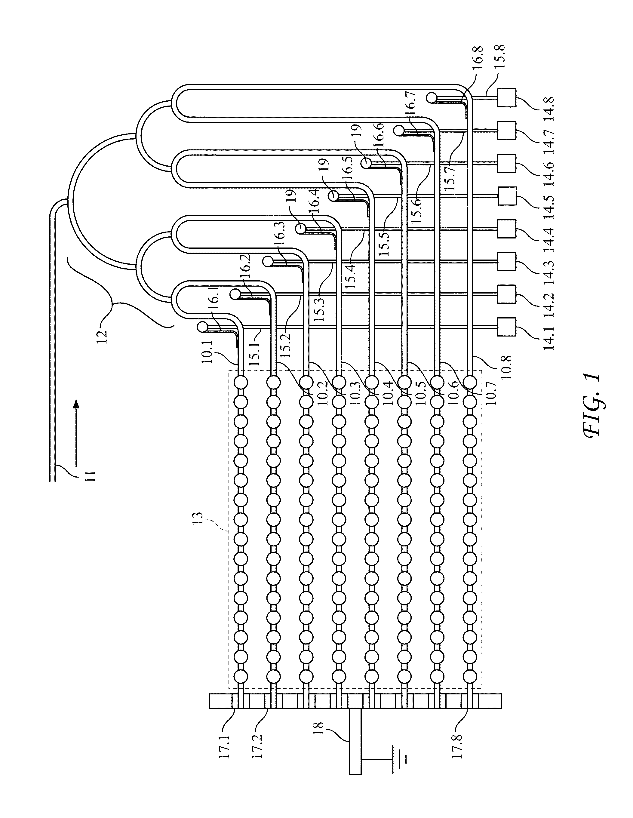
[0056]We performed a numerical simulation of the performance of a device substantially as described above. FIG. 6 provides a view of the nanoantenna array on which the simulation was based. As seen in the figure, waveguides 61 feed the optical signal into respective rows of array 61. Each of the rows extends in the direction that, for purposes of the simulation, is defined to be the direction of the x-axis. The waveguides, in the vicinity of the nanoantenna array, are likewise directed along the x-axis. The nanoantenna array is oriented in the plane formed by the x- and y-axes. Accordingly, each row is separated from its preceding row by a shift directed along the y-axis. As will further be seen in the figure, the nanoarray consists of eight rows, each containing sixteen nanoantenna elements.

[0057]The individual nanoantenna elements are dimensioned as square apertures 500 nm by 500 nm. They are spaced with a period of 1 micrometer. The optical wavelength is 3.39 micrometer...


PUM


Abstract

An optical beam-steering apparatus is provided. The apparatus includes one or more optical waveguides and at least one row of metallic nanoantenna elements overlying and electromagnetically coupled to a respective waveguide. In each such row, individual nanoantenna elements are spaced apart along an optical propagation axis of the waveguide so that there is an optical propagation phase delay between successive pairs of nanoantenna elements along the row. The apparatus also includes a respective single electric heating element in thermal contact with each of the waveguides. Each heating element is arranged to heat, substantially uniformly, at least that portion of its waveguide that directly underlies the corresponding row of nanoantenna elements.

Description


Claims


Application Information

Patent Timeline
Owner NAT TECH & ENG SOLUTIONS OF SANDIA LLC
Why Eureka
Try Eureka