Steerable hall effect thruster having plural independently controllable propellant injectors and a frustoconical exhaust outlet

Active Publication Date: 2016-11-15
SN DETUDE & DE CONSTR DE MOTEURS DAVIATION S N E C M A
View PDF5 Cites 3 Cited by
  • Summary
  • Abstract
  • Description
  • Claims
  • Application Information

AI Technical Summary

Benefits of technology

[0028]FIG. 3 is a diagrammatic perspective view of a geostationary satellite fitted with

Problems solved by technology

This implies in particular an electrical power supply circuit for the thrusters that is quite complex.
Nevertheless, such a pivot mount presents a considerable amount of mechanical complexity, and it requires moving parts that always run the risk of jamming in the very severe environment of a space vehicle.
The orientation of the thrust can thus be varied by varying the magnetic field, which presents drawbacks for maintaining the magnetic enclosure around the entire perimeter of the open end of the annular cathode, and thus for maintaining the virtual cathode grid.
Furthermore, the electric

Method used


Image

  • Steerable hall effect thruster having plural independently controllable propellant injectors and a frustoconical exhaust outlet
  • Steerable hall effect thruster having plural independently controllable propellant injectors and a frustoconical exhaust outlet
  • Steerable hall effect thruster having plural independently controllable propellant injectors and a frustoconical exhaust outlet

Examples


Embodiment Construction

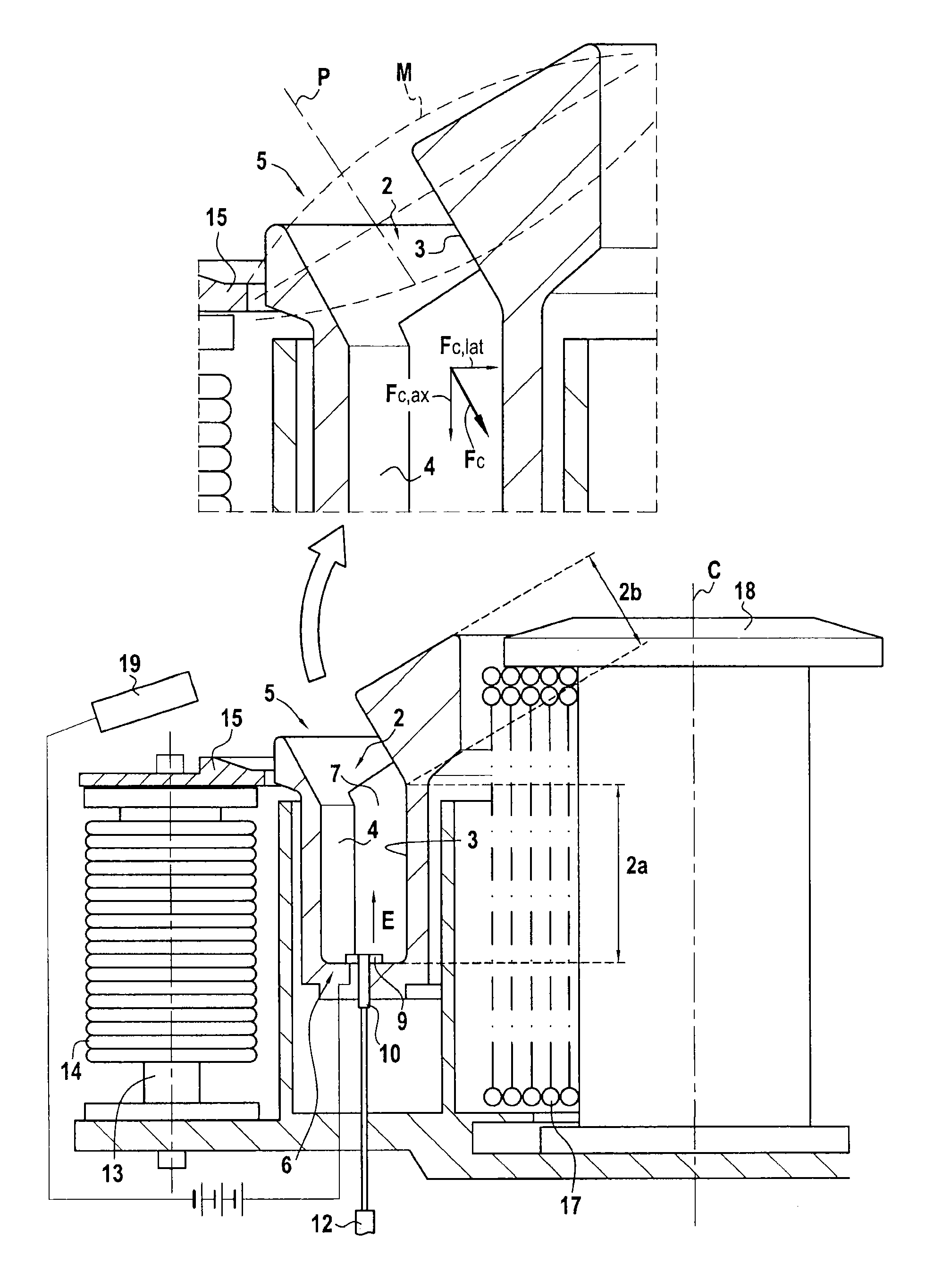
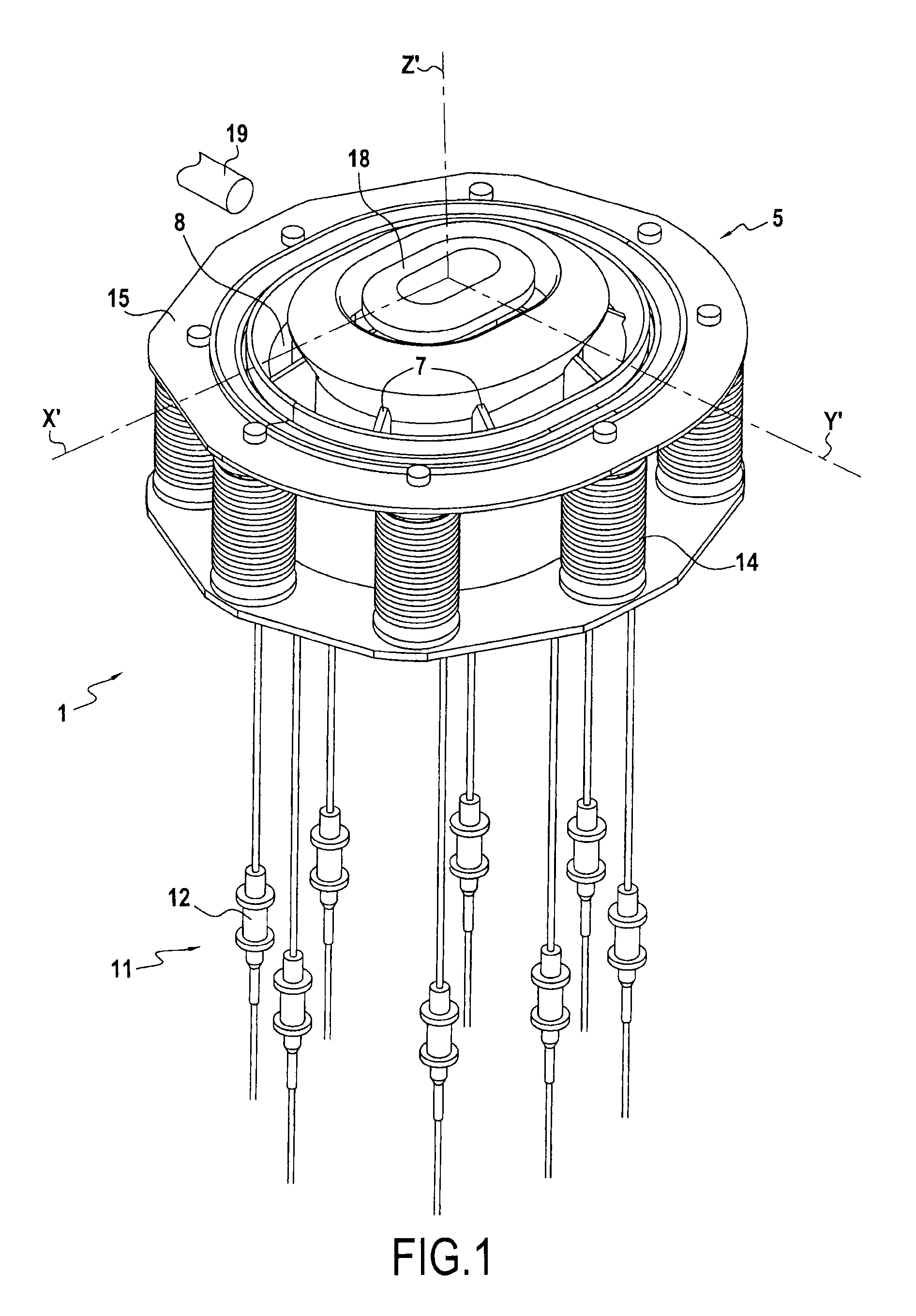
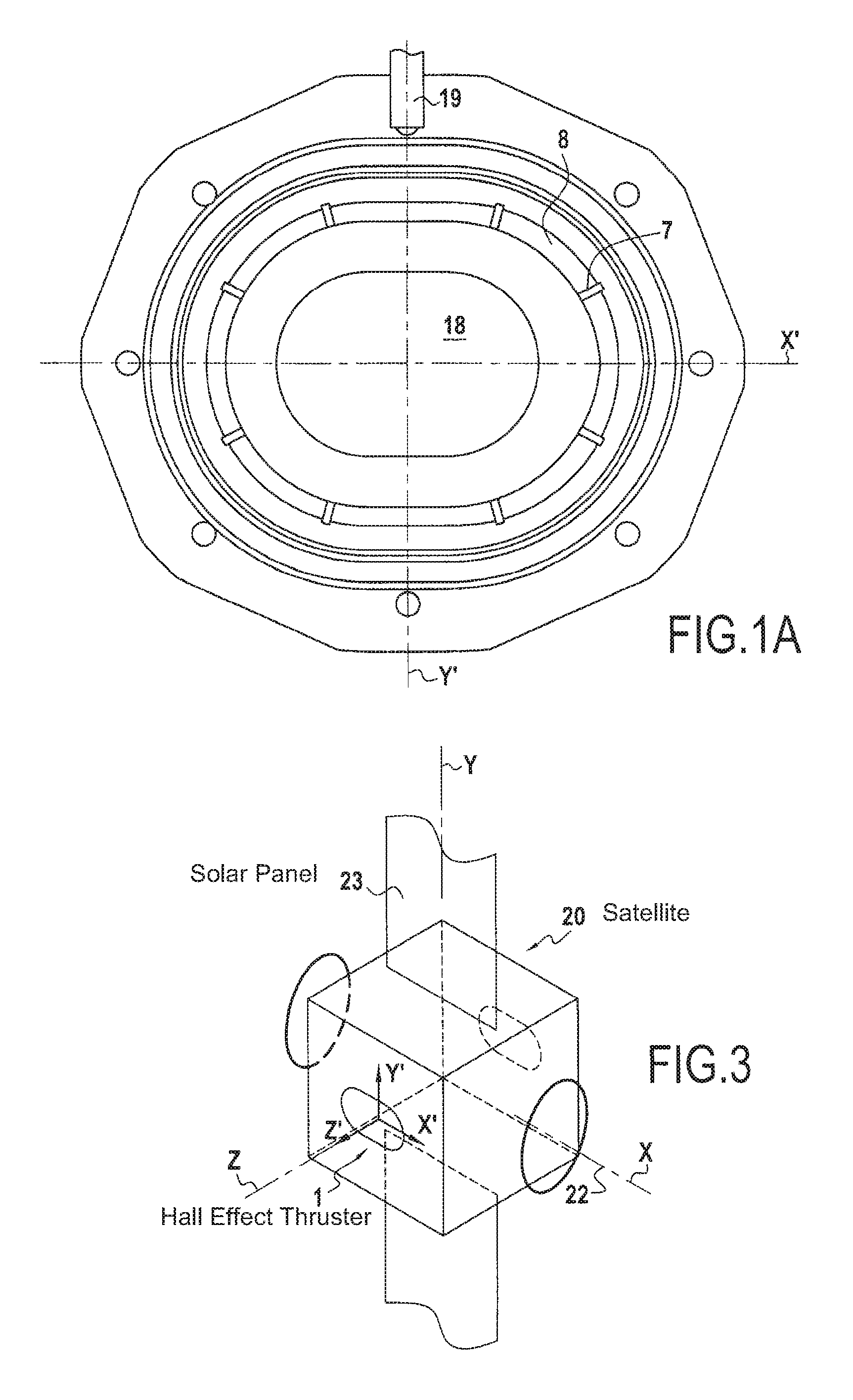
[0029]FIGS. 1, 1A, and 1B are various views of the same Hall effect thruster 1 in an embodiment. The thruster 1 has an annular channel 2 defined by two concentric walls 3 and 4 about a central axis Z′, which walls are made of ceramic material. The annular channel 2 has an open end 5 and a closed end 6. Beside the closed end 6, radial walls 7 subdivide an upstream segment 2a of the annular channel 2 into separate compartments 8. At its closed end 6, the annular channel 2 also has an anode 9, which may be segmented among the various compartments 8, and a nozzle 10 for injecting propulsion gas into each compartment 8. The nozzles 10 are connected to a source of propulsion gas by an injection circuit 11 including an individual flow rate regulator device 12 for each nozzle 10. By way of example, each device 12 may be a pencil valve or a thermo-capillary, i.e. a capillary with heater means enabling its temperature to be varied actively and thus enabling the flow rate passing through it to...


PUM


Abstract

A steerable-thrust Hall effect thruster in which a final stage of a magnetic circuit includes an inner pole and a facing outer pole, the inner pole being offset axially downstream relative to the outer pole, so that a magnetic field is inclined relative to a transverse plane of the thruster.

Description

BACKGROUND OF THE INVENTION[0001]1. Field of the Invention[0002]The present invention relates to the field of Hall effect thrusters.[0003]2. Description of Related Art[0004]The invention relates more particularly to a steerable-thrust Hall effect thruster having an annular channel, an anode, an injection circuit, a magnetic circuit, and a cathode. The annular channel is defined by two concentric walls with a central axis, having an open end and a closed end, and it includes an upstream segment beside the closed end that is subdivided by radial walls into a plurality of separate compartments. The anode is situated at the closed end of the annular channel. The injection circuit is suitable for injecting a propulsion gas, e.g. such as xenon, into the compartments of the annular channel, and it includes at least one individual flow rate regulator device for each compartment. The magnetic circuit is suitable for generating a magnetic field at the open end of the annular channel. The cath...

Claims


Application Information

Patent Timeline
IPC IPC(8): F03H1/00B64G1/40
CPCF03H1/0006B64G1/405F03H1/0062F03H1/0068F03H1/0075
Inventor MARCHANDISE, FREDERIC RAPHAEL JEANLORAND, ANTHONY CLAUDE BERNARDVIAL, VANESSA MARJORIE
Owner SN DETUDE & DE CONSTR DE MOTEURS DAVIATION S N E C M A
Why Eureka
Try Eureka