Method of driving an arc-discharge lamp

a technology of arc-discharge lamps and drivers, which is applied in the direction of electrical devices, instruments, light sources, etc., can solve the problems of low light output modulation, sudden jolt or displacement, and persistent light output, and achieve the effect of suppressing the low-frequency fluctuation of luminous flux

Inactive Publication Date: 2015-08-11
LUMILEDS
View PDF16 Cites 0 Cited by
  • Summary
  • Abstract
  • Description
  • Claims
  • Application Information

AI Technical Summary

Benefits of technology

[0008]A physical displacement or deflection of the discharge arc of the lamp can be caused by a sudden movement or mechanical excitation of the lamp, for example when the lamp is jolted. In the case of an automotive front-lighting lamp, such a jolt or displacement can occur when the car drives over a pothole or other uneven surface. As explained above, the alteration in discharge-arc length results in a modulation of the lamp voltage, which in turn would result in a modulation of the light output, which can persist for a noticeable length of time. An obvious advantage of the method according to the invention is that any mechanically induced fluctuation in luminous flux is quickly suppressed or cancelled out, so that the annoying flicker effect that would otherwise follow a jolt to the lamp is essentially prevented from developing.
[0015]There are a number of possible ways to detect a change in luminous flux arising on account of a sudden displacement of the discharge arc. In one preferred embodiment of the invention, the mechanically induced fluctuation in luminous flux of the lamp is detected by monitoring the lamp voltage, since the light output is closely related to the lamp voltage. This approach is also advantageous since essentially all known lamp drivers more or less continually monitor the lamp voltage for their power-control algorithms, making it a fairly straightforward matter to detect a change in lamp voltage.
[0016]Lamp voltage values collected over time can then be used to deduce whether a power correction is necessary to suppress a low-frequency fluctuation in luminous flux. In a preferred embodiment of the invention, therefore, the characteristic of the mechanically induced fluctuation in luminous flux of the lamp comprises a lamp voltage modulation envelope, which lamp voltage modulation envelope is derived from a sequence of monitored lamp voltage values. By observing the lamp voltage and measuring its value over time, any discrepancy between ‘normal’ behaviour and behaviour as a result of a discharge-arc displacement can be relatively easily detected. For example, if the lamp voltage is always measured at a particular instant of the lamp period, this lamp voltage value should always be about the same in a time frame of a few seconds. In case of a sudden arc displacement, however, the lamp voltage becomes disturbed, and the measured lamp voltage values will accordingly exhibit a certain deviation from the expected value. The measured values indicate the trend taken by the lamp voltage as it is caused to fluctuate. This information can be used, as will be explained below, to correct the lamp power and to cancel out the fluctuations in luminous flux.

Problems solved by technology

In the case of an automotive front-lighting lamp, such a jolt or displacement can occur when the car drives over a pothole or other uneven surface.
As explained above, the alteration in discharge-arc length results in a modulation of the lamp voltage, which in turn would result in a modulation of the light output, which can persist for a noticeable length of time.

Method used


Image

  • Method of driving an arc-discharge lamp
  • Method of driving an arc-discharge lamp
  • Method of driving an arc-discharge lamp

Examples


Embodiment Construction

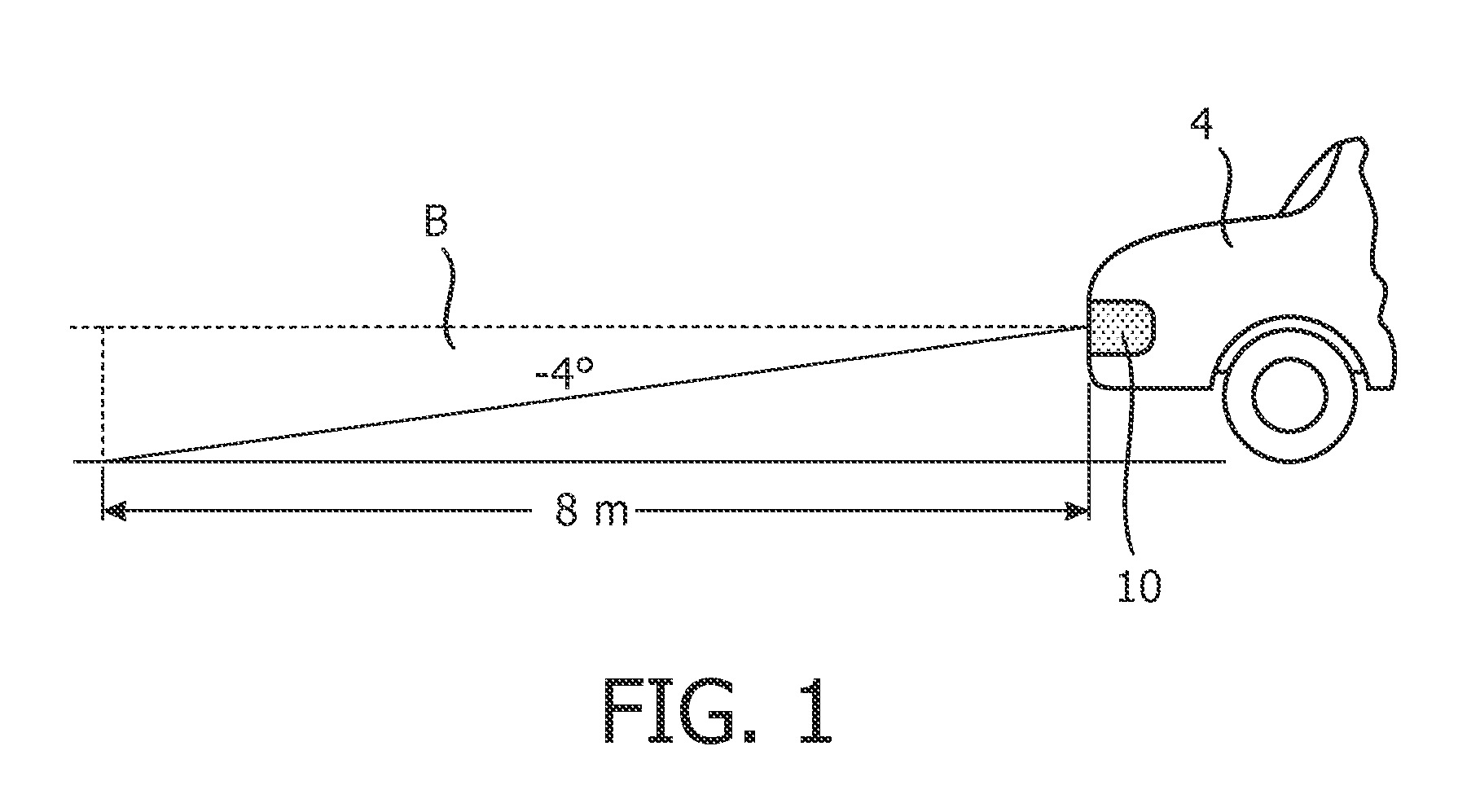
[0033]FIG. 1 shows an automobile front beam issued by a front headlamp of a vehicle. For an automobile, the region in which the perceptible and annoying forefront flicker originates is generally up to about 8 metres in front of the vehicle and in the beam region up to about 4° below a horizontal plane of the headlamp.

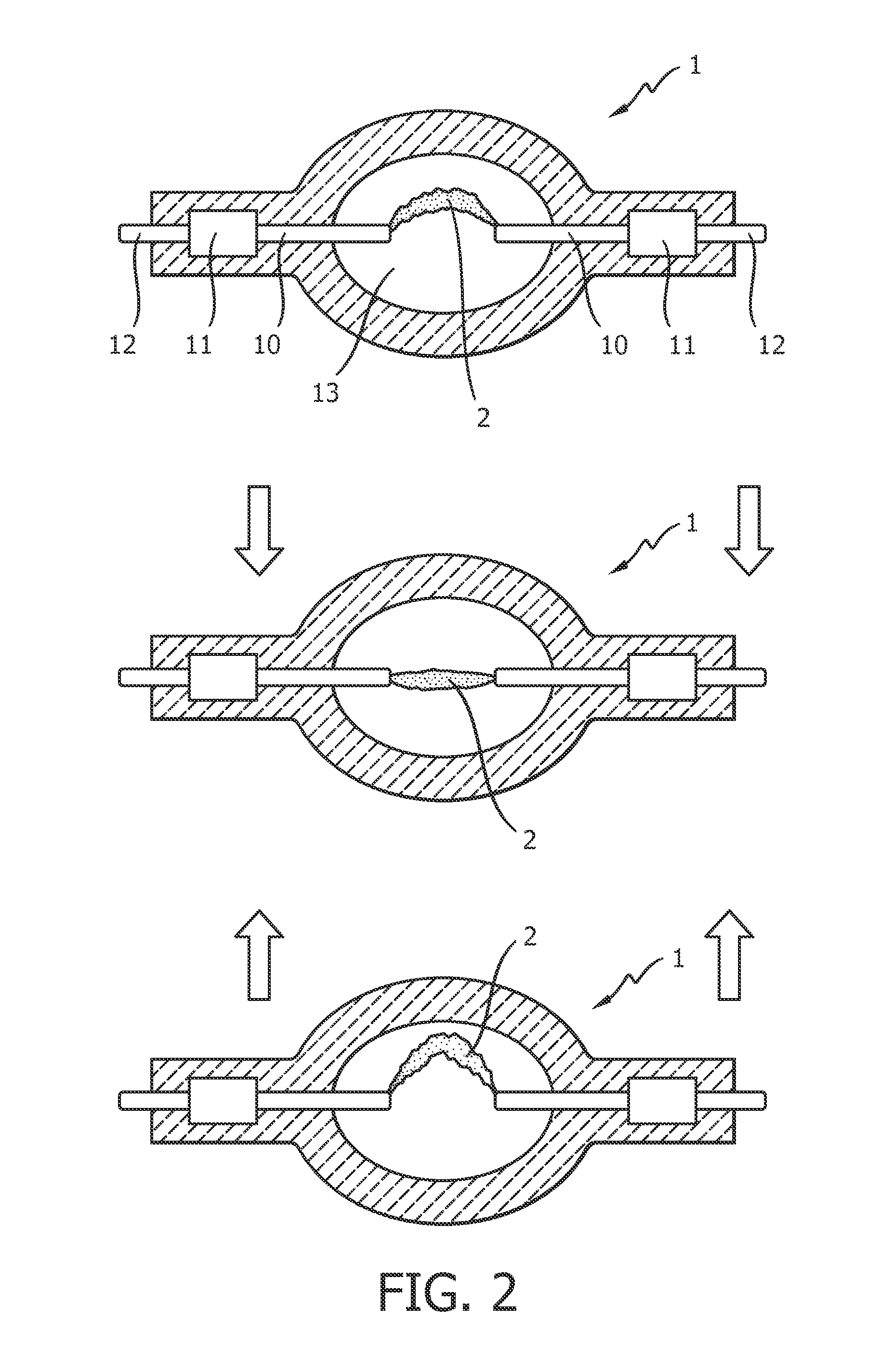
[0034]FIG. 2 shows a simplified schematic representation of an arc-discharge lamp 1 with a discharge-arc 2 extending between two electrodes 10. In normal operation, as indicated in the upper part of the diagram, owing to an upward convection in the burner, the discharge arc extends as shown between the two electrodes 10. When the lamp 1 is subject to an abrupt downward displacement, shown in the centre part of the diagram and indicated by the downward arrow, the discharge arc 2 is briefly ‘shortened’ as shown. This shorter discharge-arc is associated with a decrease in lamp voltage, and therefore also with a decrease in luminous flux. Similarly, when the lamp 1 is subje...


PUM


Abstract

The invention describes a method of driving an arc-discharge lamp (1), which method comprises the steps of detecting a mechanically induced fluctuation in luminous flux of the lamp (1) occurring as a result of a physical displacement of the discharge arc (2), determining a characteristic (43, 51, 63) of the mechanically induced fluctuation in luminous flux of the lamp (1), and adjusting the lamp power on the basis of the determined characteristic (43, 51, 63) to suppress the mechanically induced fluctuation in luminous flux of the lamp (1). The invention further describes a driver (3) for an arc-discharge lamp (1), which driver comprises a detecting means (40, 50, 60) for detecting a mechanically induced fluctuation in luminous flux of the lamp (1) occurring as a result of a physical displacement of the discharge arc (2), a determination unit (42, 50, 62) for determining a characteristic (43, 51, 63) of the mechanically induced fluctuation in luminous flux of the lamp (1); and an adjustment unit (8) for adjusting a lamp power (Pc) on the basis of the determined characteristic (43, 51, 63) to suppress the mechanically induced fluctuation in luminous flux of the lamp (1). The invention also describes a lighting assembly (9) comprising a high-intensity gas-discharge lamp (1) and such a driver (3) for driving the lamp (1) according to the inventive method.

Description

FIELD OF THE INVENTION[0001]The invention describes a method of driving an arc-discharge lamp, a driver for an arc-discharge lamp, and a lighting assembly.BACKGROUND OF THE INVENTION[0002]A measure of the performance of a lamp can be given by the efficacy of the lamp in lumens / Watt, i.e. the luminous flux produced by the lamp as a ratio of the power required to produce that luminous flux. For many lighting applications, a constant light-flux—and therefore a constant efficacy—is desirable. For lamps such as high-intensity gas-discharge (HID) lamps that operate by applying an alternating voltage across two electrodes, some fluctuation can occur at the relatively high operating frequency of the lamp. As the lamp ages, the electrode topology changes, causing variations in the length of the discharge arc and an associated fluctuation in lamp voltage, since the lamp voltage is directly related to the length of the discharge arc. It follows that the light output also fluctuates, since the ...

Claims


Application Information

Patent Timeline
Patent Type & Authority Patents(United States)
IPC IPC(8): H05B41/00H05B41/292
CPCH05B41/2928
Inventor RIEDERER, XAVERDABRINGHAUSEN, LARS
Owner LUMILEDS
Why Eureka
Try Eureka