
Grain bin aeration

a technology for aerating bins and grains, which is applied in the direction of drying machines, manufacturing tools, light and heating equipment, etc., can solve the problems of difficulty in installing grains in existing bins and limited length of horizontal tube networks in hoppers

Active Publication Date: 2015-08-18
HARTSOOK JEREMY
View PDF13 Cites 1 Cited by
  • Summary
  • Abstract
  • Description
  • Claims
  • Application Information

AI Technical Summary

Benefits of technology

Enables easy installation and adjustment of aeration ducts in hopper bottom bins, ensuring efficient airflow without obstructing grain discharge, and accommodating varying bin sizes and air flow rates.

Problems solved by technology

Since the floor of a hopper bottom bin slopes, the length of a horizontal tube network in the hopper is limited.
A problem with hopper bin aeration duct systems is the difficulty of installing them in existing bins.

Method used


Image

  • Grain bin aeration
  • Grain bin aeration
  • Grain bin aeration

Examples


Embodiment Construction

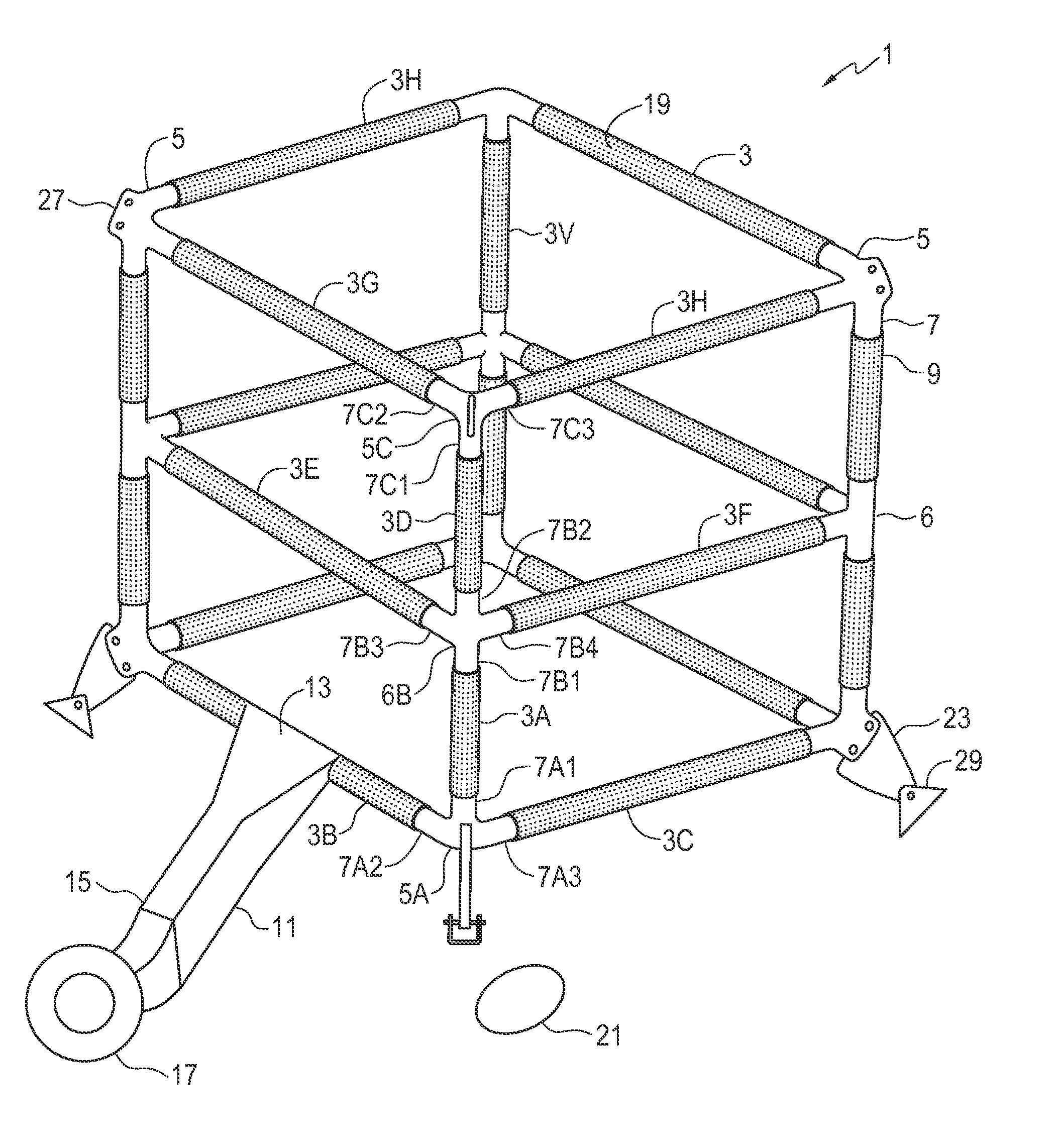
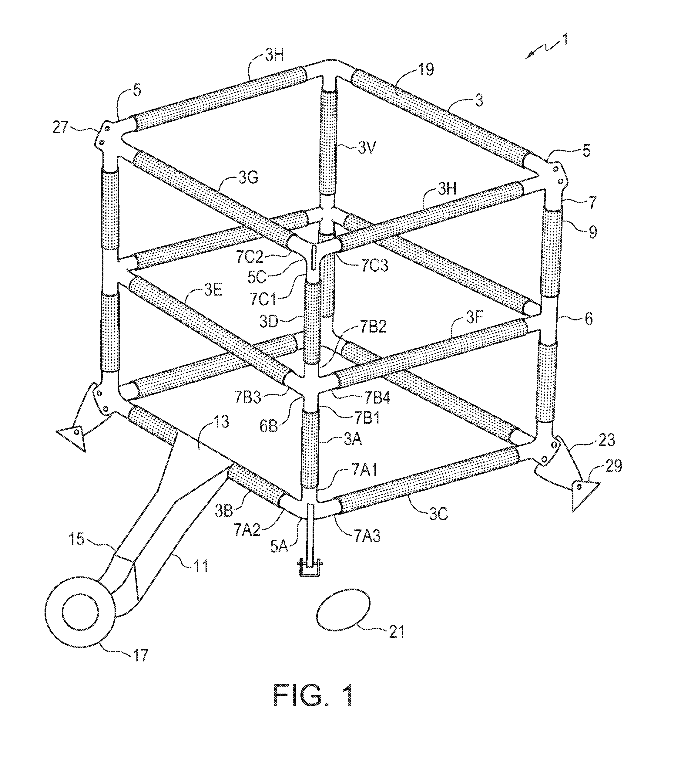
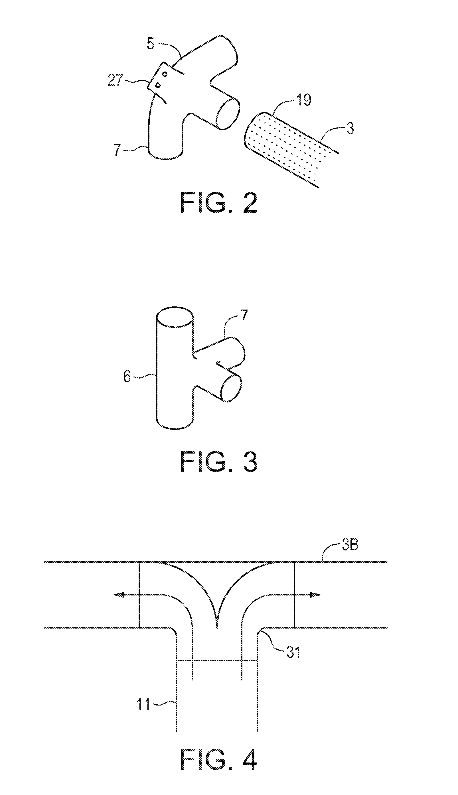
[0023]FIG. 1 schematically illustrates an embodiment of an aeration duct apparatus 1 of the present invention. The illustrated apparatus 1 comprises a plurality of aeration tubes 3, and a plurality of corner hollow connectors 5 and middle hollow connectors 6. Each corner hollow connector 5 defines three connection ports 7, and each middle hollow connector 6 defines four connection ports 7 as schematically illustrated in FIGS. 2 and 3. Each aeration tube 3 is connected at each tube end 9 thereof to one of the connection ports 7, and each connection port 7 is connected to a tube end 9 such that the connected aeration tubes 3 and hollow connectors 5, 6 form a substantially rigid structure as illustrated.

[0024]A transition duct 11 is connected to one of the aeration tubes 3 at an inside end 13 thereof and is adapted at an outside end 15 thereof for attachment to a fan 17. As can be readily seen in the illustrated structure, the aeration tubes 3 and transition duct 11 are configured such...


PUM

PropertyMeasurementUnit
diameteraaaaaaaaaa
areaaaaaaaaaaa
lengthaaaaaaaaaa

Abstract

An aeration duct apparatus has a plurality of aeration tubes connected together by hollow connectors, each hollow connector defining at least three connection ports. Each aeration tube is connected at each tube end thereof to one of the connection ports, and each connection port is connected to a tube end such that the connected aeration tubes and hollow connectors form a substantially rigid structure. A transition duct is connected to one of the aeration tubes at an inside end thereof and is adapted at an outside end thereof for attachment to a fan. The aeration tubes and transition duct are configured such that air can flow from the fan through the transition duct into each aeration tube and out through a perforated area of walls of the aeration tubes.

Description

FIELD[0001]This invention is in the field of grain storage and aeration bins and in particular an aeration duct apparatus that is well suited for hopper bottom grain bins with floors sloping to a discharge opening.BACKGROUND[0002]Aeration systems are used to prevent spoilage in stored grain, and to reduce the moisture content of the grain. Such systems include a perforated duct located inside the bin, and a fan directing air into the duct, out through the perforations and up through the grain and out through a vent in the roof of the bin. The fan and perforated duct area are sized to provide the desired airflow for the height and volume of grain in the bin. The perforated duct area must be large enough to provide sufficient open spaces so that the required volume of air can flow through the perforations without developing excessive back-pressure.[0003]Providing sufficient perforated area in flat bottom bins is not usually a problem as the duct can be provided by a perforated floor a...

Claims


Application Information

Patent Timeline
Patent Type & Authority Patents(United States)
IPC IPC(8): F26B5/00F26B19/00A23B9/08B23P19/00F26B9/10
CPCF26B19/00A23B9/08B23P19/00F26B9/103Y10T29/49826
Inventor HARTSOOK, JEREMY
Owner HARTSOOK JEREMY
Learn More