Supercharge Your Innovation With Domain-Expert AI Agents!

Dielectric ceramic and laminated ceramic capacitor

a technology of laminated ceramic and dielectric ceramic, which is applied in the direction of fixed capacitor details, inorganic insulators, fixed capacitors, etc., can solve the problems of significant decrease in high-temperature load life, and achieve the effects of reducing high-temperature load life, and improving high-temperature load li

Active Publication Date: 2015-08-18
MURATA MFG CO LTD
View PDF14 Cites 2 Cited by
  • Summary
  • Abstract
  • Description
  • Claims
  • Application Information

AI Technical Summary

Benefits of technology

[0010]The present invention has been achieved in view of these circumstances, and an object of the present invention is to provide a dielectric ceramic that can achieve a sufficient high-temperature load life even when a high electric field is applied for a long period of time in the case of reduction in layer thickness to on the order of 1 μm, with desired high reliability, and a laminated ceramic capacitor manufactured with the use of the dielectric ceramic.
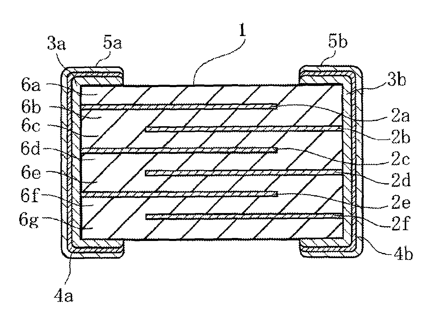
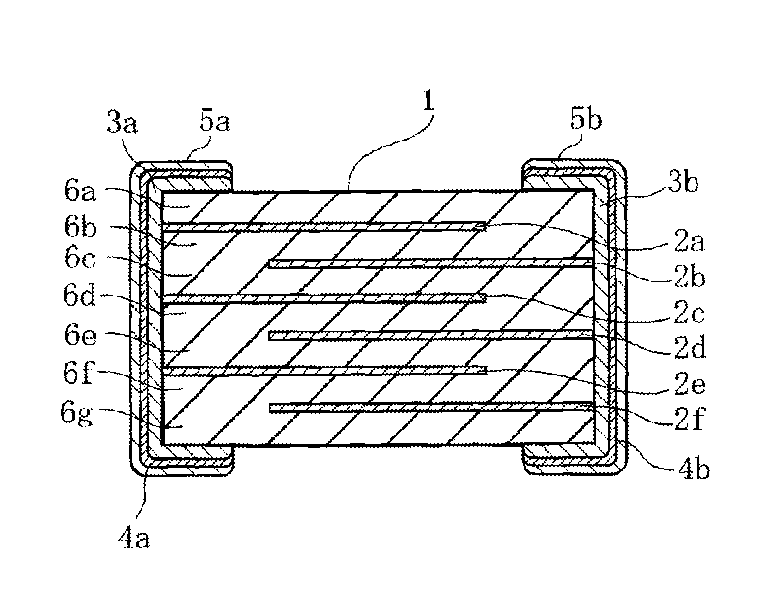
[0030]In addition, in the laminated ceramic capacitor according to the present invention, the dielectric layers are formed from the dielectric ceramic according to any of the aspects of the present invention and, a laminated ceramic capacitor can be thus achieved which can achieve an adequate high-temperature load life with high reliability, even when a high electric field of 20 kV / mm or more is applied to the dielectric layers reduced in thickness to on the order of 1 μm.

Problems solved by technology

In particular, the proportion of heterogeneous-phases in crystal grains is increased as the dielectric ceramic layers are reduced in thickness to on the order of 1 μm, and thus, when a high electric field of 20 kV / mm or more is applied to the dielectric ceramic layers with these heterogeneous-phases formed therein, there is a possibility of causing a significant decrease in high-temperature load life.

Method used


Image

  • Dielectric ceramic and laminated ceramic capacitor
  • Dielectric ceramic and laminated ceramic capacitor

Examples


example 1

Preparation of Samples

[0074](Sample Numbers 1 to 6)

[0075]High-purity BaCO3, CaCO3, and TiO2 were prepared as ceramic raw materials, and these ceramic raw materials were weighed for the molar substitution x and compounding molar ratio m of Ca as shown in Table 1. Then, these weighed materials were put along with PSZ balls and pure water into a ball mill, subjected to sufficient mixing and grinding in a wet way, and to drying, and then subjected to calcination at a temperature of 1050° C. for about 2 hours, thereby preparing main constituent powders with an average grain size of 0.20 μm (synthesis of main-phase grains).

[0076]Next, Y2O3, SiO2, MgO, MnCO3, and V2O5 were prepared as accessory constituent powders. Then, these accessory constituent powders were weighed for the contents of Y, Si, Mg, Mn, and V in terms of parts by mol as shown in Table 1 with respect to 100 parts by mol of the Ti contained in the main constituent powder, and subjected to wet mixing in a ball mill, and to a ...

example 2

[0121]High-purity BaCO3, CaCO3, and TiO2 were prepared as ceramic raw materials, and these ceramic raw materials were weighed for the molar substitution x and compounding molar ratio m of Ca as shown in Table 3. Then, these weighed materials were put along with PSZ balls and pure water into a ball mill, subjected to sufficient mixing and grinding in a wet way, and to drying, and then subjected to calcination at a temperature of 1000 to 1200° C. for about 2 hours, thereby preparing main constituent powders with an average grain size of 0.20 μm (synthesis of main-phase grains).

[0122]Next, Y2O3, SiO2, MgO, MnCO3, and V2O5 were prepared as accessory constituent powders. Then, these accessory constituent powders were weighed for the contents of Y, Si, Mg, Mn, and V in terms of parts by mol as shown in Table 3 with respect to 100 parts by mol of the Ti contained in the main-phase grains, and subjected to wet mixing in a ball mill, and to a drying treatment to obtain ceramic raw material p...

example 3

[0141]High-purity BaCO3, CaCO3, and TiO2 were prepared as ceramic raw materials, and these ceramic raw materials were weighed for the molar substitution x and compounding molar ratio m of Ca as shown in Table 4. Then, these weighed materials were put along with PSZ balls and pure water into a ball mill, subjected to sufficient mixing and grinding in a wet way, and to drying, and then subjected to calcination at a temperature of 1000 to 1200° C. for about 2 hours, thereby preparing main constituent powders with an average grain size of 0.20 μm.

[0142]Next, a rare-earth oxide Re2O2 (Re: Gd, Tb, Dy, Ho, Er, Tm, and Yb) was prepared, and SiO2, MgO, MnCO3, and V2O5 were further prepared. Then, these materials were weighed for the contents of the rare-earth element Re, Si, Mg, Mn, and V in terms of parts by mol as shown in Table 4 with respect to 100 parts by mol of the Ti in the main constituent powder, and subjected to wet mixing in a ball mill, and to a drying treatment to obtain cerami...


PUM

PropertyMeasurementUnit
thicknessaaaaaaaaaa
electric fieldaaaaaaaaaa
equivalent circle diameteraaaaaaaaaa

Abstract

A dielectric ceramic that contains, as its main constituent, main-phase grains including a perovskite-type compound containing Ba, Ca, and Ti; first heterogeneous-phase grains containing Ca, a rare-earth element, and Si; and second heterogeneous-phase grains containing no Ca and containing the rare-earth element and Si. The second heterogeneous-phase grains are present in the dielectric ceramic in a ratio of 0.05 or less (including 0) of the number of the second heterogeneous-phase grains to the total of the first heterogeneous-phase grains and the second heterogeneous-phase grains. In the first heterogeneous-phase grains, the content of Ca is preferably 8% or more in terms of molar ratio with respect to the total content of Ca, the rare-earth element, and Si.

Description

CROSS REFERENCE TO RELATED APPLICATIONS[0001]The present application is a continuation of International application No. PCT / JP2012 / 056576, filed Mar. 14, 2012, which claims priority to Japanese Patent Application No. 2011-057415, filed Mar. 16, 2011, the entire contents of each of which are incorporated herein by reference.FIELD OF THE INVENTION[0002]The present invention relates to a dielectric ceramic and a laminated ceramic capacitor, and more particularly, to a dielectric ceramic suitable for a dielectric material for a small-sized and high-capacitance laminated ceramic capacitor, and a laminated ceramic capacitor manufactured with the use of the dielectric ceramic.BACKGROUND OF THE INVENTION[0003]With the development of electronics technology in recent years, the reduction in size and the increase in capacitance have been rapidly advanced on laminated ceramic capacitors. Further, with the reduction in size and increase in capacitance for laminated ceramic capacitors, dielectric...

Claims


Application Information

Patent Timeline
Patent Type & Authority Patents(United States)
IPC IPC(8): C04B35/468H01G4/10C04B35/626H01B3/12H01G4/12H01G4/30H01G4/018
CPCH01G4/018C04B35/4682C04B35/62685H01B3/12H01G4/1227H01G4/30C04B2235/3206C04B2235/3208C04B2235/3224C04B2235/3225C04B2235/3239C04B2235/3262C04B2235/3427C04B2235/3454C04B2235/652C04B2235/6562C04B2235/6567C04B2235/6582C04B2235/6584C04B2235/6588C04B2235/79C04B2235/80C04B35/468H01G4/12
Inventor YAMAGUCHI, SHINICHI
Owner MURATA MFG CO LTD
Features
  • R&D
  • Intellectual Property
  • Life Sciences
  • Materials
  • Tech Scout
  • Unparalleled Data Quality
  • Higher Quality Content
  • 60% Fewer Hallucinations
Learn More