Al/AlN joint material, base plate for power module, power module, and manufacturing method of Al/AlN joint material

a technology of al/aln joint material and power module, which is applied in the direction of electrical apparatus construction details, metal adhesion improvement, and improvement of insulation substrate adhesion, etc., can solve the problems of low strength of aln base plate itself, insufficient joint strength, and inability to improve reliability. , to achieve the effect of high joint strength, good reliability and high strength

Active Publication Date: 2009-05-12
MITSUBISHI MATERIALS CORP
View PDF34 Cites 18 Cited by
  • Summary
  • Abstract
  • Description
  • Claims
  • Application Information

AI Technical Summary

Benefits of technology

[0012]The present invention was made in view of the aforementioned issues, and its first object is to provide a power module and a base plate therefore in which a high joint strength of a metal plate and a ceramic base plate can be obtained.
[0041]In addition, according to an Al / AlN joint material of the present invention, a sufficient heat-resistance cycle and a sufficient life can be obtained without peeling between the insulated base plate and the heat-releasing object and warpage or cracking in the insulated base plate and the heat releasing object, not only in the initial joint strength but also when repeating thermal expansion and contraction due to a temperature cycle. Therefore, the Al / AlN joint material, a ceramic circuit base plate using the Al / AlN joint material, and a power module using the Al / AlN joint material can be obtained.

Problems solved by technology

However, the following issues remain in the art of the conventional power module base plate.
That is, as the first issue, when joining the metal plate of the ceramic base plate, there is a disadvantage in that sufficient joint strength cannot be obtained even though the surface roughness of the ceramic base plate is decreased simply, and reliability cannot be improved.
In addition, as the second issue, when using AlN base plate as the insulated base plate, the strength of the AlN base plate itself is low.
Therefore, if a temperature cycle is repeated in using the power module, there may be a case in which a crack is formed thereon and the metal circuit plate peels.
As a result, there has been a problem of a low heat-resistance cycle in which the heat releasing performance of the power module decreases and the operational reliability of the electric device also decreases.
Therefore, it is difficult to directly join the Al metal layer on the AlN base plate, and BN is removed from the surface layer of the AlN base plate by honing or the like before joining the Al circuit layer or the Al metal layer.
However, even though sufficient initial joint strength can be obtained by removing BN, it is difficult to secure a sufficient heat-resistance cycle when repeating a temperature cycle, and the life of the power module greatly varies.
For this reason, the performance of the power module has not been sufficient for purposes which are expected to increase such as electric automobiles or in-house power generation for personal use, in which the temperature cycle is frequently repeated.

Method used


Image

  • Al/AlN joint material, base plate for power module, power module, and manufacturing method of Al/AlN joint material
  • Al/AlN joint material, base plate for power module, power module, and manufacturing method of Al/AlN joint material
  • Al/AlN joint material, base plate for power module, power module, and manufacturing method of Al/AlN joint material

Examples


specific example 1

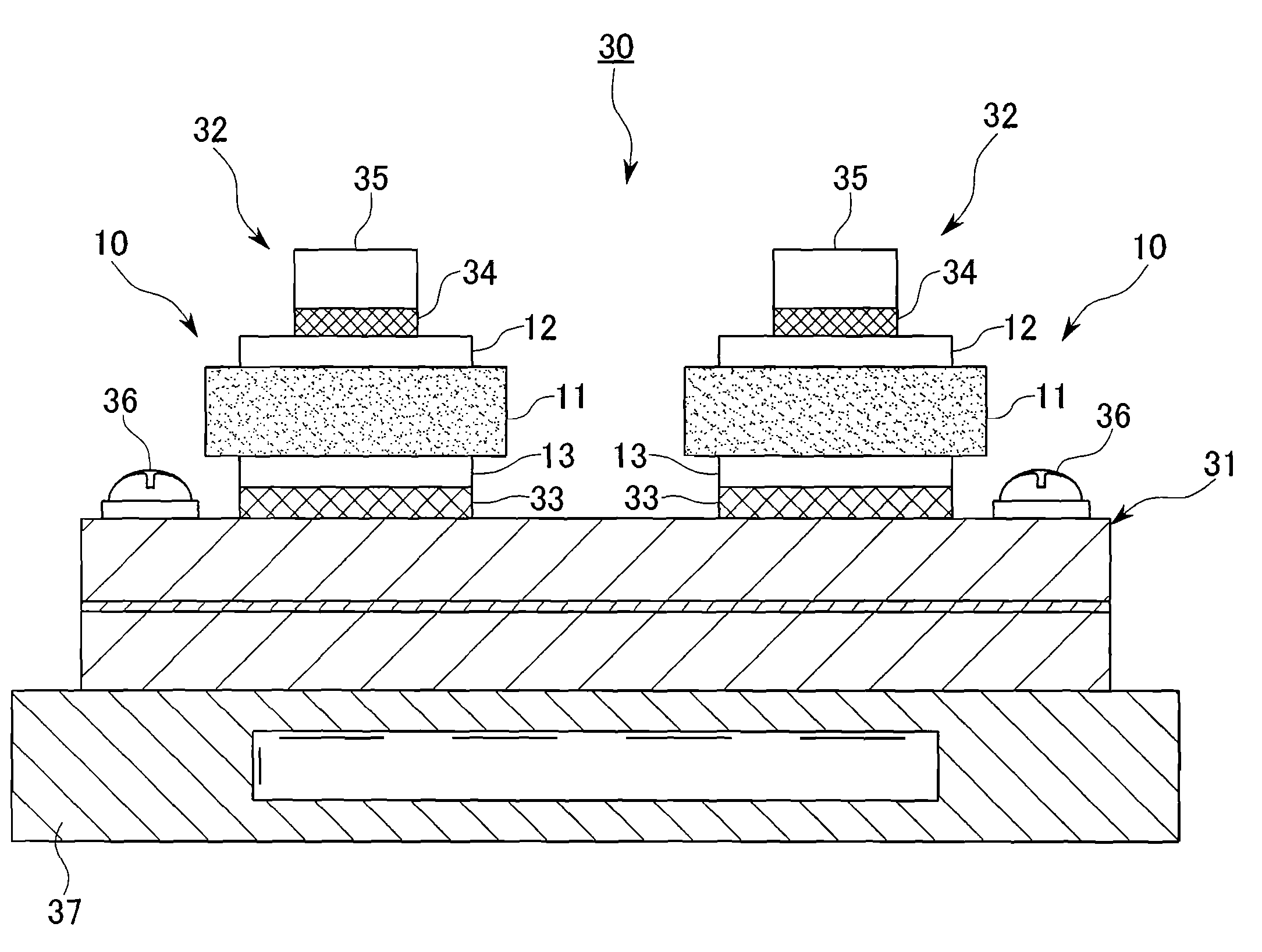
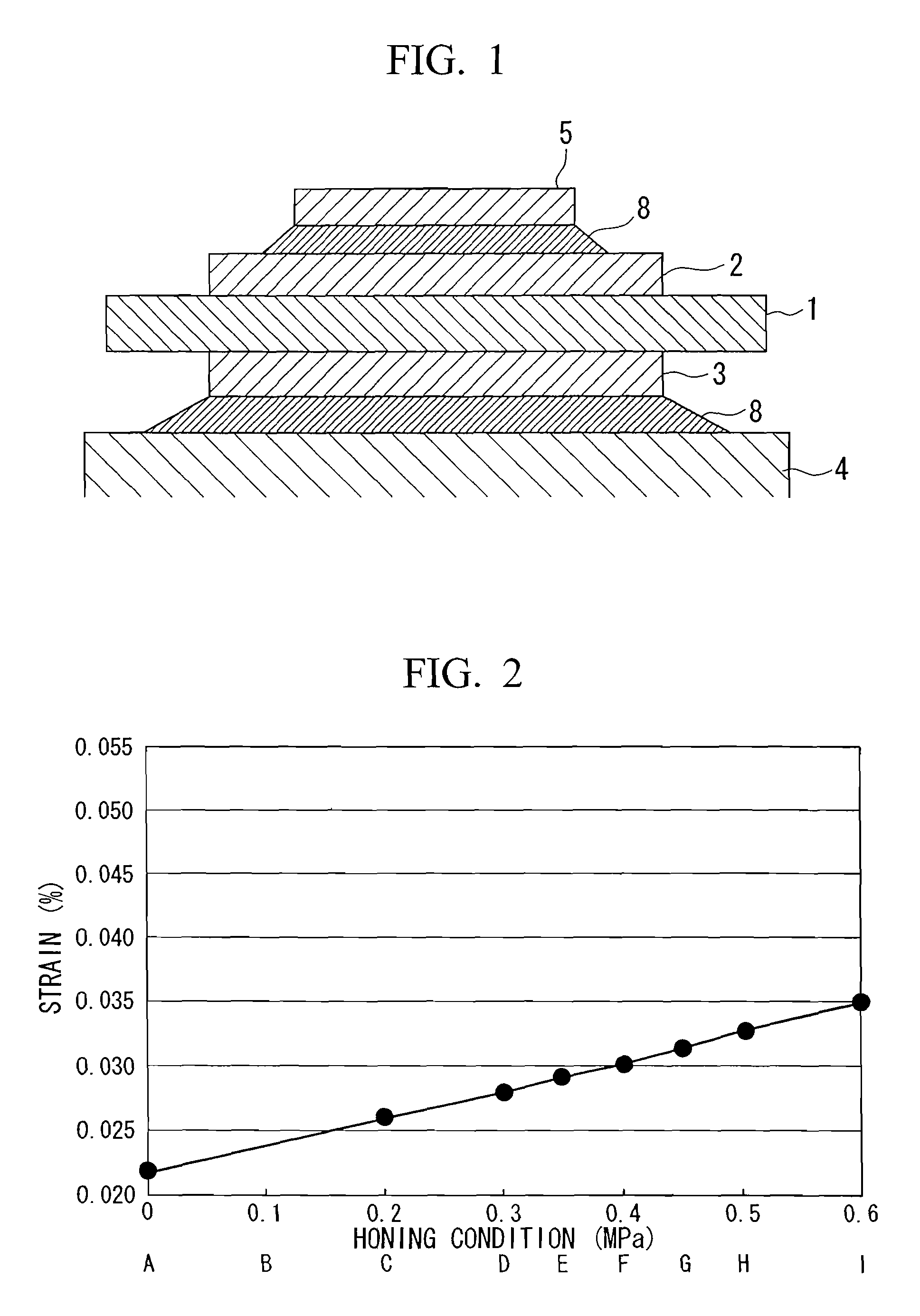
[0098]The power module base plate of the present invention shall be described more specifically by a specific example. First, samples of the AlN ceramic base plate 1 (50 mm×30 mm, 0.635 mm in thickness) indicated by reference symbols A to J were surface-treated under different conditions. The metal circuit plate 2 made of Al with a purity more than 99.9% (100 mm×5 mm width, 0.4 mm in thickness) and the metal plate 3 made of Al with a purity more than 99.9% (50 mm×30 mm width, 0.4 mm in thickness) were laminated and joined on both faces of each sample A to J, with the Al—Si foil (50 mm×5 mm width, 0.1 mm in thickness) being sandwiched therebetween. Joint surfaces were evaluated and joint strengths were measured for the samples manufactured in this manner.

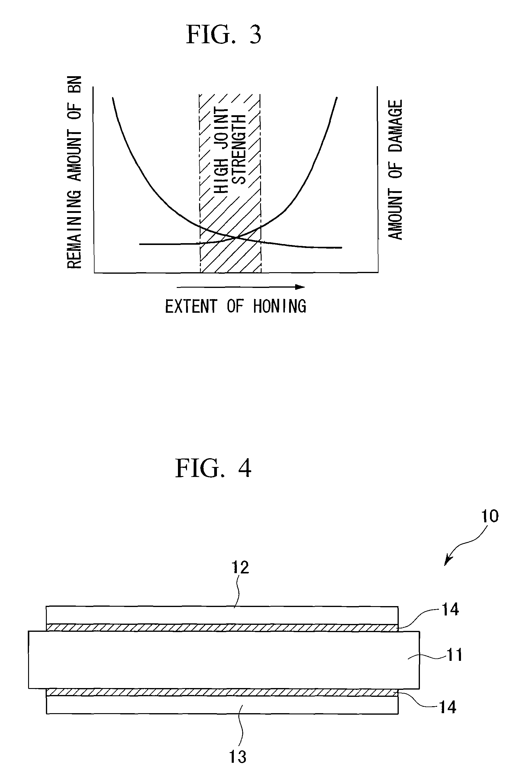
[0099]To change the damage amount on their surfaces, honing was performed on each sample Ato J, under a different honing number expressed by reference numerals 1 to 3 and different honing pressure expressed by weak, intermediate, and...

specific example 2

[0147]The second specific example of the present invention shall be described.

[0148]AlN base plates whose materials were honed under different pressures before joining were temperature cycle tested (−45° C. to 125° C.). It was checked whether or not there was peeling by ultrasonography every 1000 cycles, and the greatest temperature cycle number without peeling was determined as the life of the base plate.

[0149]The cross section near the AlN / Al interface was observed by a scanning electron microscope (SEM), and the depth of the three-dimensional network structure was measured by element surface analysis of the infiltration depth in the AlN base plate of Si included in the Al component using an electron probe X-ray microanalyzer (EPMA).

[0150]The maximum height Ry was measured by a surface roughness measurement (manufactured by Mitsutoyo Corp., Surftest501), and specific surface area was measured by a laser microscope (manufactured by KEYENCE Corp., VK8550). Both the maximum height an...


PUM

PropertyMeasurementUnit
purityaaaaaaaaaa
surface roughnessaaaaaaaaaa

Abstract

A base plate for a power module includes: a metal plate, a ceramic base plate joined to the metal plate, and a release agent which includes boron provided in a joint surface between the metal plate and the ceramic base plate. A remaining amount of the release agent is less than 5, as an amount of boron measured by fluorescence X-ray analysis, where the amount of boron is defined as a value obtained by an expression: (a peak height of B-Kα / a peak height of X-Kα) x 100000 and a crystal grain straining region in the joint surface is equal to or less than 40%, or an amount of crystal grain straining in the joint surface is equal to or less than 0.03%.

Description

TECHNICAL FIELD[0001]The present invention relates to an Al / AlN joint material, a base plate for a power module, and a power module which are used in a semiconductor device for controlling high current and high voltage of, for example, an electric automobile or an electric rolling stock, and a manufacturing method of the Al / AlN joint material.CROSS-REFERENCE TO PRIOR APPLICATION[0002]This is a U.S. National Phase Application under 35 U.S.C. §371 of International Patent Application No. PCT / JP2005 / 006618 filed Apr. 4, 2005, and claims the benefit of Japanese Patent Applications No. 2004-110879, filed Apr. 5, 2004 and 2004-221700, filed Jul. 29, 2004, all of which are incorporated by reference herein. The International Application was published in Japanese on Oct. 20, 2005 as WO 2005 / 098942 A1 under PCT Article 21(2).BACKGROUND ART[0003]Traditionally among semiconductor elements, a power module for a power supply has a relatively large heating value, and it is necessary to select a bas...

Claims


Application Information

Patent Timeline
Patent Type & Authority Patents(United States)
IPC IPC(8): H05K7/00B32B15/01B32B3/00H05K1/14H01L23/12H01L23/14H01L23/373H05K1/03H05K3/38
CPCH01L23/3735H05K3/38Y10T428/12472H01L2224/32225H01L2224/291Y10S428/91H05K1/0306Y10T29/49163Y10T428/24917Y10T428/24926Y10T428/12736Y10T428/12993H01L2924/01322H01L2924/10253H01L2924/014H01L2924/00C04B37/026C04B2237/59C04B2235/96C04B2235/963C04B2237/08C04B2237/121C04B2237/128C04B2237/366C04B2237/368C04B2237/402C04B2237/52C04B2237/55C04B2237/704C04B2237/706C04B2237/72C04B2237/708H01L23/14
Inventor NAGASE, TOSHIYUKINAGATOMO, YOSHIYUKIKUBO, KAZUAKINEGISHI, TAKESHI
Owner MITSUBISHI MATERIALS CORP
Why Eureka
Try Eureka