Ceramic center pin for compaction tooling and method for making same

a technology of center pins and compaction tools, applied in the field of center pins and punches, can solve the problems of high friction level applied to the interior of the die surface, need to change out and rework such tooling, and high wear level of compaction tooling, so as to reduce the cost of reworking the same, the life of compaction center pins and other tooling may be significantly increased, and the tool life is sufficien

Active Publication Date: 2006-08-31
BLUE SKY VISION PARTNERS
View PDF54 Cites 18 Cited by
  • Summary
  • Abstract
  • Description
  • Claims
  • Application Information

AI Technical Summary

Benefits of technology

[0013] In accordance with an aspect of the present invention, there is provided an apparatus for forming a powder material into a solid form through the application of pressure, comprising: a die; a lower compression punch insertable into a lower end of said die, said lower compression punch having a ceramic-tipped center pin passing therethrough where the ceramic reduces the wear of said outer surface of said center pin; means for filling at least a portion of the cavity defined by said die, said lower compression punch, and said center pin with the powder material; and an upper compression punch, insertable into an upper end of said die to compact the powder material.
[0017] The techniques described herein are advantageous because they can be adapted to any of a number of compaction tooling applications. In addition, they can be used in other similar compaction embodiments to allow for the use of ceramic materials in high-friction environments where tool steels and other surface hardening processes fail to provide sufficient improvement in tool life. The techniques of the invention are advantageous because they provide a range of alternatives, each of which is useful in appropriate situations. As a result of the invention, the life of compaction center pins and other tooling may be significantly increased and the cost of reworking the same may be reduced.BRIEF DESCRIPTION OF THE DRAWINGS

Problems solved by technology

During the compaction process, however, the application of significant compressive forces results in a high friction level applied to the interior of the die surface in region 30 and to the exterior of the center pin tip in region 31.
This friction force causes a high level of wear on the compaction tooling, resulting in the frequent need to change out and rework such tooling.
Although it is known to employ ceramics in the interior region of the die, to reduce the wear from friction, ceramics have not been successfully employed on the center pin tip because of the difficulty in reliably affixing the ceramic to the center pin.
Although a ceramic coating may be provided on a center pin tip by known methods, e.g. arc plasma spray coating, such coatings have not been found to be satisfactory.
Thus, it is often the case that the dies considerably outlast the center pins and that frequent replacement and rework of center pins continues to be a problem that plagues the powder compaction industry.
It will be appreciated that solid ceramic center pins may be produced, however, they are believed to be cost prohibitive and difficult to repair and rework.

Method used


Image

  • Ceramic center pin for compaction tooling and method for making same
  • Ceramic center pin for compaction tooling and method for making same
  • Ceramic center pin for compaction tooling and method for making same

Examples


Embodiment Construction

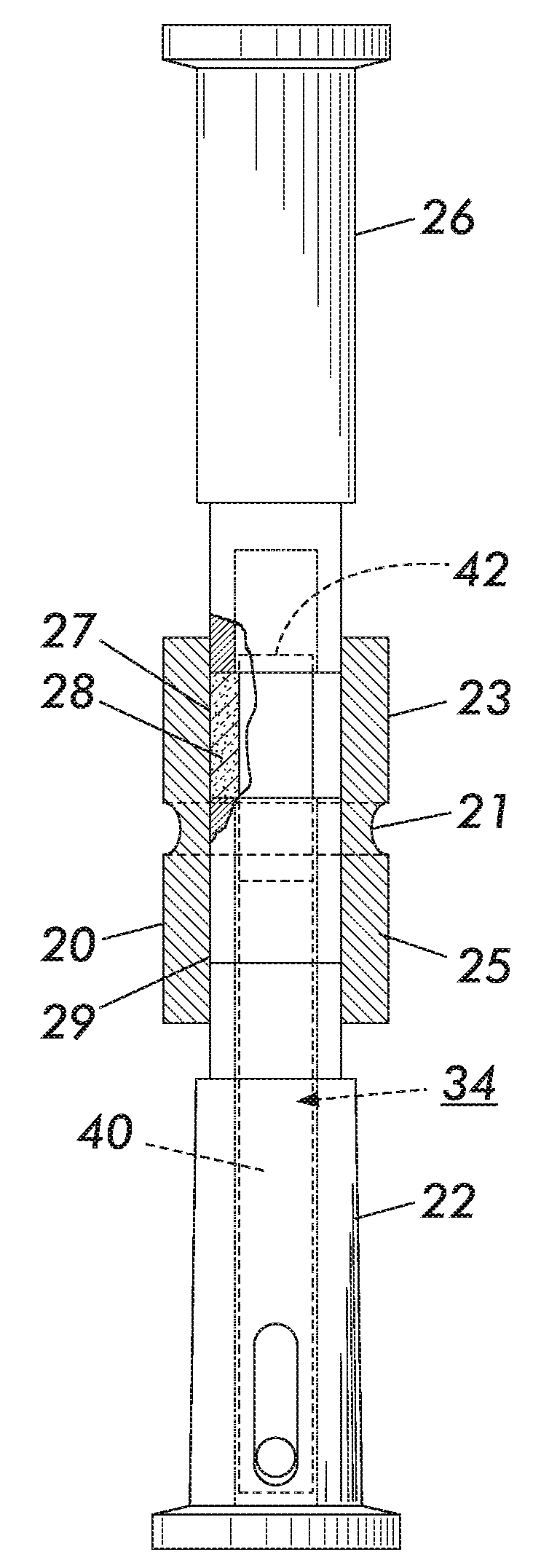
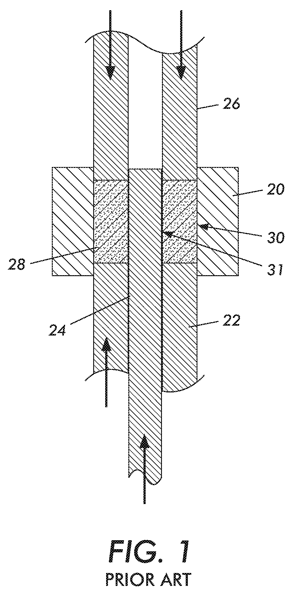
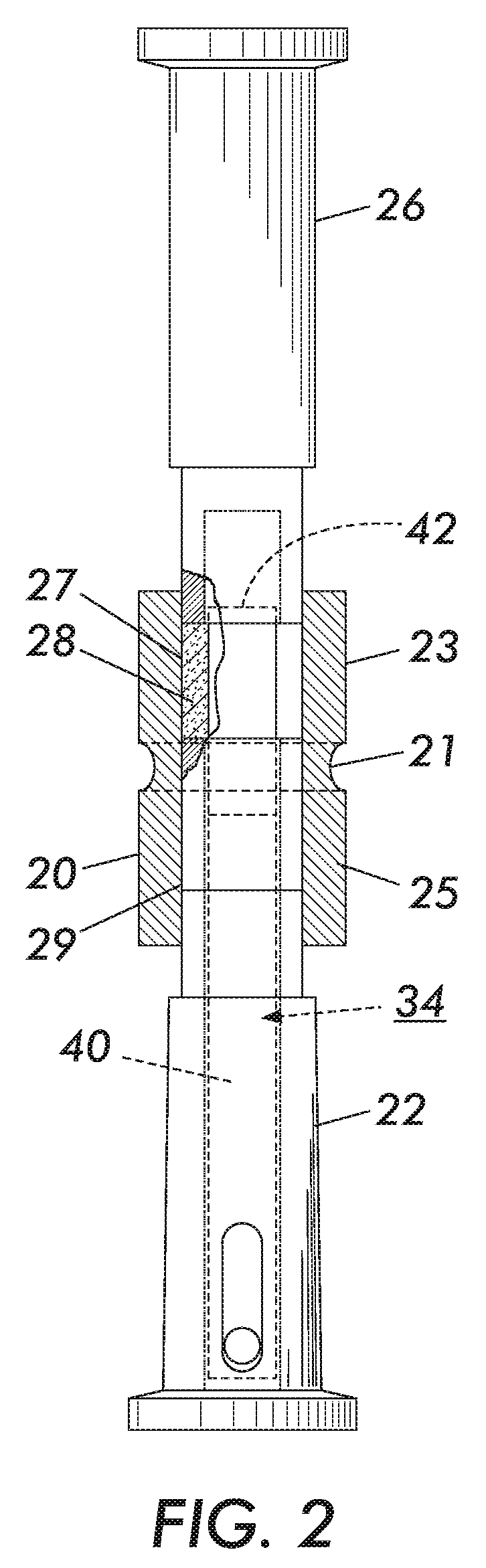
[0028] For a general understanding of the present invention, reference is made to the drawings. In the drawings, like reference numerals have been used throughout to designate identical elements.

[0029] Reference may also be had to Table 1, “Glossary Of Ceramic Terms”, and Table 2, “General Descriptions of Structural Ceramic Materials”, both Innex Industries, Inc. internal publications. Tables 1 and 2 are incorporated herein for their teachings of terms and properties related to ceramic materials used in the present invention.

TABLE 1GLOSSARY OF CERAMIC TERMS: ZIRCONIA WEAR PARTSTERMDEFINITIONDensityMass per unit volume of a substance(metric units: g / cm3, Kg / m3)StrengthThe stress (force per area) required to rupture, crack, fracture,Flexural strengthbreak the materialModulus of Rupture, MORHigh strength needed for impact and thermal shock3 or 4-point-bend strengthFlaws cause fracture in ceramics and must be controlled by(metric units: MPa, GPa)careful processingToughnessToughness i...


PUM

PropertyMeasurementUnit
diameteraaaaaaaaaa
adhesiveaaaaaaaaaa
sizesaaaaaaaaaa

Abstract

The present invention is a method and apparatus for the production of compacted powder elements. More specifically, the present invention is directed to the improvement of tooling for powder compaction equipment, and the processes for making such tooling. The improvement comprises the use of a ceramic tip or similar component in high wear areas of the tooling, particularly center pins. Moreover, the use of such ceramic components enables reworking and replacement of the worn tool components.

Description

[0001] This application is a Continuation of, and claims priority benefit from, U.S. patent application Ser. No. 10 / 320,331, filed Dec. 16, 2002, for a “CERAMIC CENTER PIN FOR COMPACTION TOOLING AND METHOD FOR MAKING SAME,” by L. Gakovic, which also claims the benefit from U.S. Provisional Application No. 60 / 371,816, filed Apr. 11, 2002 for a “CERAMIC CENTER PIN FOR COMPACTION TOOLING AND METHOD FOR MAKING SAME,” by Luka Gakovic, both applications are hereby incorporated by reference in their entirety. [0002] This invention relates generally to compaction tooling components, and more particularly to a compaction tool, such as a center pin, incorporating a tip or wear surface comprising a ceramic component and the method for manufacturing and assembling such a center pin.BACKGROUND AND SUMMARY OF THE INVENTION [0003] The present invention is directed to improvements in the tooling used in compaction equipment and tableting machines, and particularly the tooling used in the equipment ...

Claims


Application Information

Patent Timeline
Patent Type & Authority Applications(United States)
IPC IPC(8): B30B11/04B30B15/06
CPCB30B15/065Y10T29/49742Y10T29/49735Y10T29/4973Y10T29/49732Y10T29/49739Y10T29/49744Y10T29/49716Y10T29/49737
Inventor GAKOVIC, LUKA
Owner BLUE SKY VISION PARTNERS
Why Eureka
Try Eureka