Surgical clip applier

a technology of surgical clip and applicator, which is applied in the field of surgical instruments, can solve the problem that the instruments tend to be relatively complex

Active Publication Date: 2015-08-25
TYCO HEALTHCARE GRP LP
View PDF840 Cites 121 Cited by
  • Summary
  • Abstract
  • Description
  • Claims
  • Application Information

AI Technical Summary

Benefits of technology

[0016]In use, when the head of the clip follower is positioned between the pair of jaws, the head of the clip follower may prevent the pair of jaws from closing and thus prevents the at least one handle from actuating completely.

Problems solved by technology

Inevitably, these instruments tend to be relatively complex, including many parts, many of which move and cooperate with one another.

Method used


Image

  • Surgical clip applier
  • Surgical clip applier
  • Surgical clip applier

Examples


Embodiment Construction

[0101]Embodiments of surgical clip appliers in accordance with the present disclosure will now be described in detail with reference to the drawing figures wherein like reference numerals identify similar or identical structural elements. As shown in the drawings and described throughout the following description, as is traditional when referring to relative positioning on a surgical instrument, the term “proximal” refers to the end of the apparatus which is closer to the user and the term “distal” refers to the end of the apparatus which is further away from the user.

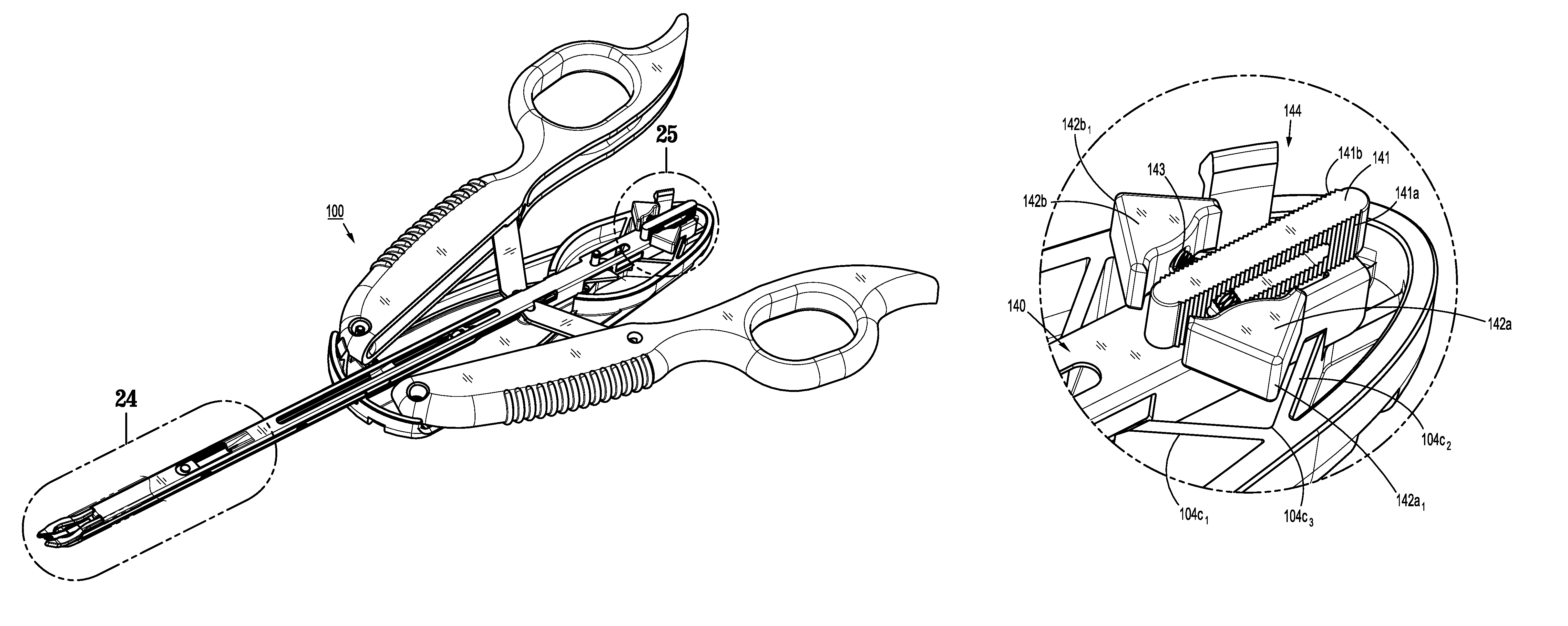
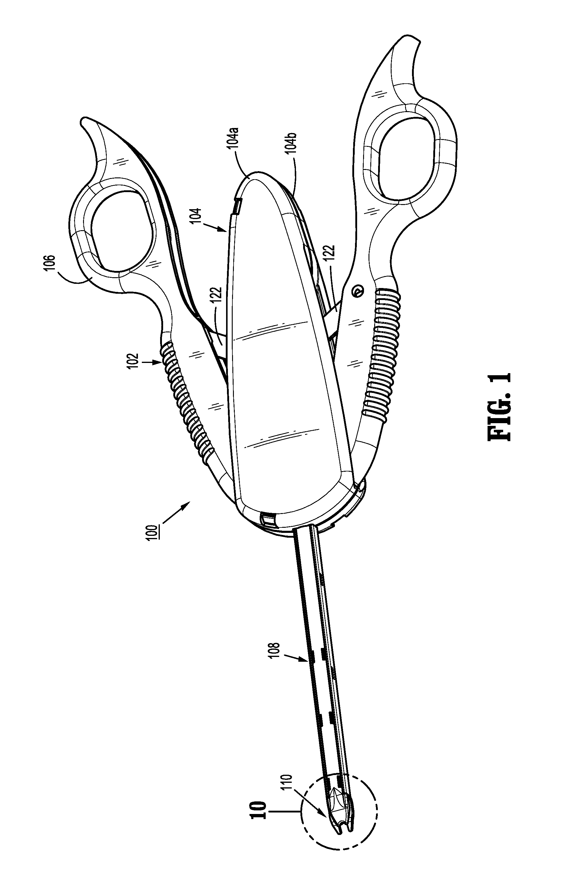
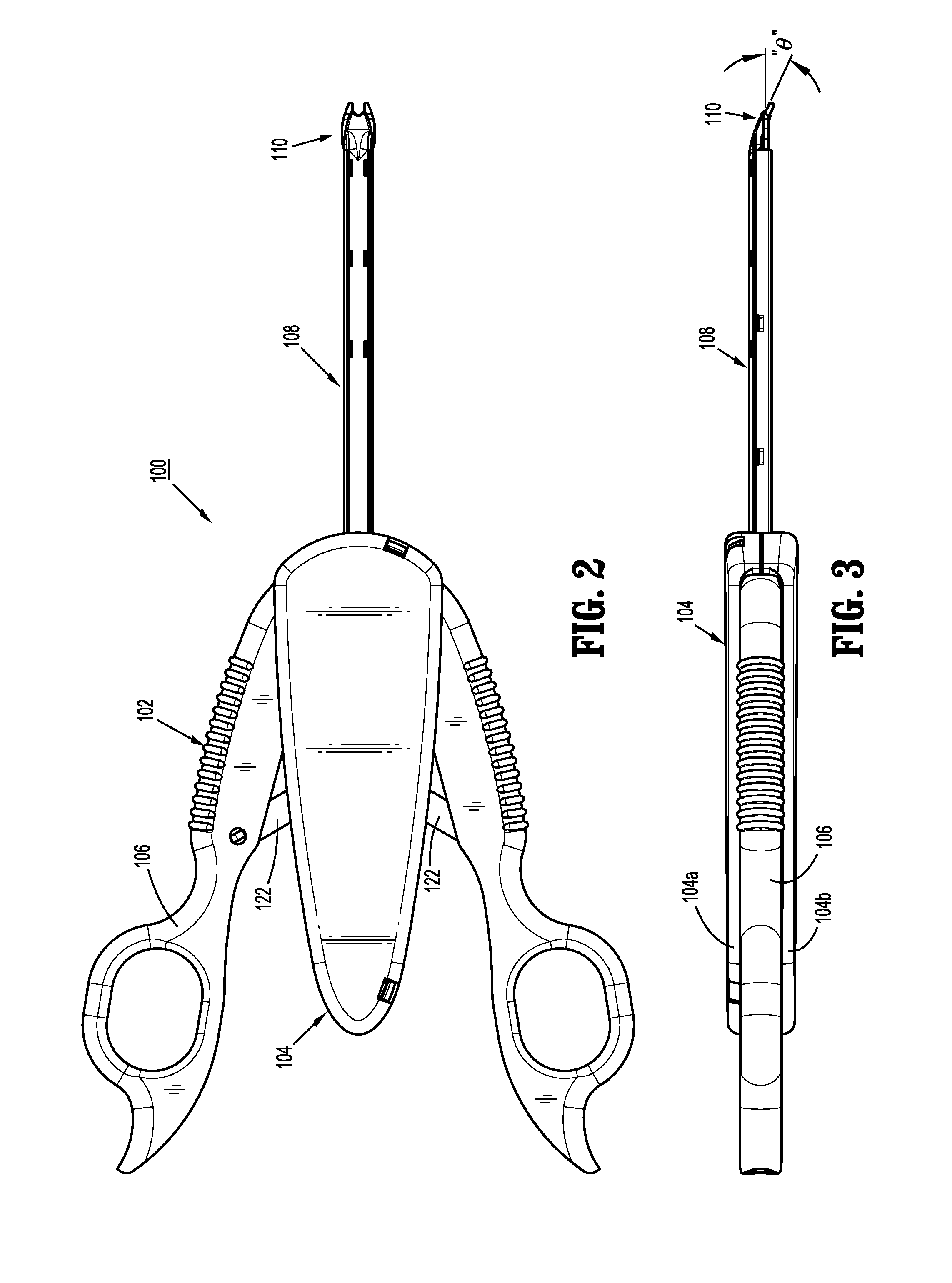
[0102]Turning initially to FIGS. 1-3, a surgical instrument that is capable of applying a number of hemostatic clips to selected tissue for occlusion purposes during open surgical procedures is generally designated as 100.

[0103]Clip applier 100 includes a handle assembly 102 including a housing 104 having an upper housing half 104a and lower housing half 104b. Handle assembly 102 further includes a pair of handles 106 ...


PUM


Abstract

A surgical clip applier is provided and includes a ratchet mechanism having a rack member connected to a drive channel such that axial translation of the drive channel results in axial translation of the rack member, the rack member defining a first set of teeth along a first side thereof and a second set of teeth along a second side thereof. The ratchet mechanism including a first pawl and a second pawl each tiltably supported in the housing and disposed on respective opposed sides of the rack member; and a buckling spring interposed between the first pawl and the second pawl and constrained in a slot formed in the rack member, wherein the buckling spring is dimensioned so as to bow in one of a proximal direction and a distal direction.

Description

BACKGROUND[0001]1. Technical Field[0002]The present application relates to surgical instruments, and more particularly, to surgical clip appliers having a plurality of clips for applying the clips to body tissues and vessels during surgical procedures.[0003]2. Discussion of Related Art[0004]Surgical clip appliers are known in the art and have increased in popularity among surgeons by offering an alternative to conventional suturing of body tissues and vessels. Typical instruments are disclosed in U.S. Pat. No. 5,030,226 to Green et al. and U.S. Pat. No. 5,431,668 to Burbank, III et al. These instruments generally provide a plurality of clips which are stored in the instrument and which are fed sequentially to the jaw mechanism at the distal end of the instrument upon opening and closing of the handles at the proximal end of the instrument. As the handles are closed, the jaws close to deform a clip positioned between the jaw members, and as the jaws are opened to release the deformed...

Claims


Application Information

Patent Timeline
Patent Type & Authority Patents(United States)
IPC IPC(8): A61B17/10A61B17/128A61B17/29
CPCA61B17/1285A61B2017/2943A61B17/10A61B17/128A61B2017/00407
Inventor MALKOWSKI, JAROSLAW T.ROCKROHR, BRIAN
Owner TYCO HEALTHCARE GRP LP
Why Eureka
Try Eureka