Steering axle

a technology of steering axle and steering linkage, which is applied in the direction of steering parts, steering linkages, fluid steering, etc., can solve the problems of only being realized in practice, and achieve the effect of simple manner and good tracking of trailers

Inactive Publication Date: 2015-08-25
SCHARMULLER JOSEF +1
View PDF22 Cites 0 Cited by
  • Summary
  • Abstract
  • Description
  • Claims
  • Application Information

AI Technical Summary

Benefits of technology

[0004]Object of the invention is the provision of a steering axle of the afore-stated type which is abl

Problems solved by technology

This is often realized only in

Method used


Image

  • Steering axle
  • Steering axle
  • Steering axle

Examples


Embodiment Construction

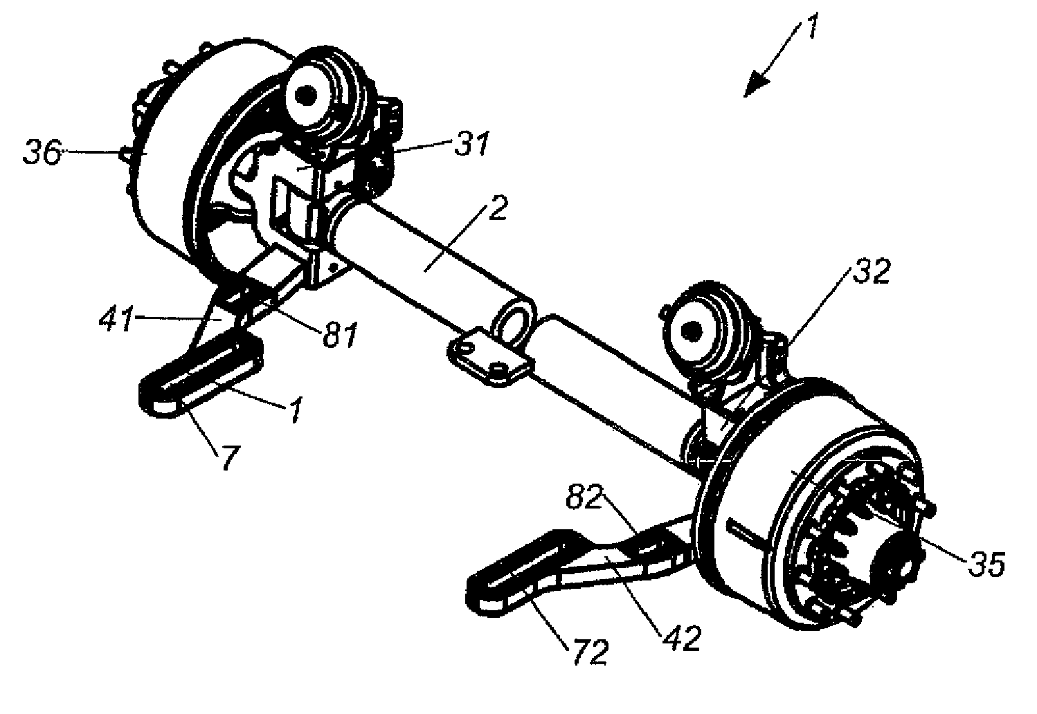
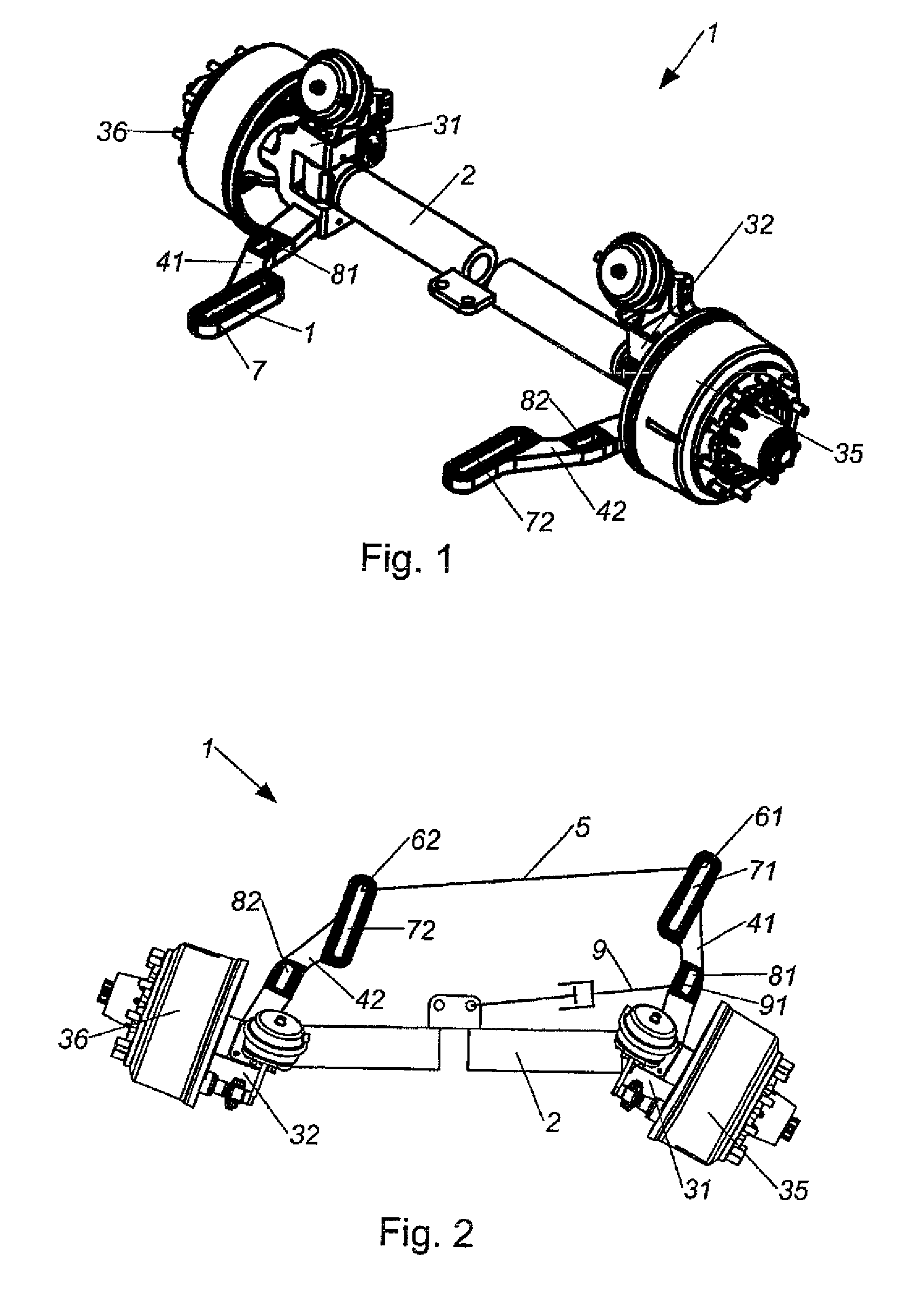
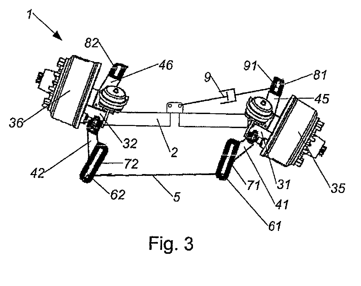
[0014]FIGS. 1 to 3 show preferred embodiments of a steering axle 1 for a vehicle, with steering levers 31, 32 being articulated on both sides of an axle body 2, and with each of the steering levers 31, 32 interacting with a track arm 41, 42, and with a tie rod 5 being pivotally connected on both ends at attack points 61, 62 to the track arms 41, 42.

[0015]Such steering axles 1 are typically used in land vehicles, wherein the vehicle may involve a driven tractor or a steered trailer. Connected to the steering levers 31, 32 are rims 35, 36 on which the wheels are mounted.

[0016]The track arms 41, 42 have an adjustment device 71, 72 for changing the position of the attack points 61, 62.

[0017]The steering axle 1 can be used in particular when power-steered trailers are involved.

[0018]The presence of the track arms 41, 42 and the tie rod 5 ensures that pivoting of one of the wheels causes a pivoting of the other one of the wheels of the steering axle 1. This ensures that not merely one of ...


PUM


Abstract

The invention relates to a steering axle (1) for a vehicle, wherein steering levers (31, 32) are articulated to both sides of an axle body (2) and each of the steering levers (31, 32) is operatively connected to a track arm (41, 42), and a tie rod (5) is hingedly connected at both ends at attack points (61, 62) to the track arms (41, 42). It is proposed to provide the track arms (41, 42) with an adjustment device (71, 72) for changing the position of the attack points (61, 62).

Description

CROSS-REFERENCES TO RELATED APPLICATIONS[0001]This application is the U.S. National Stage of International Application No. PCT / AT2012 / 000236, filed Sep. 13, 2012, which designated the United States and has been published as international Publication No. WO 2013 / 036978 and which claims the priority of Austrian Patent. Application, Serial No. A 1341 / 2011, filed Sep. 16, 2011, pursuant to 35 U.S.C. 119(a)-(d).BACKGROUND OF THE INVENTION[0002]The invention relates to a steering axle.[0003]Such steering axles are particularly used for trailers with steered axles to thereby attempt to maintain the trailer better in the track of a tractor. This is often realized only inadequately in practice however.SUMMARY OF THE INVENTION[0004]Object of the invention is the provision of a steering axle of the afore-stated type which is able to obviate the mentioned disadvantages and to ensure a good tracking of a trailer in a simple manner.[0005]This is achieved according to the invention by a steering a...

Claims


Application Information

Patent Timeline
IPC IPC(8): B62D5/20B62D13/02B62D7/18B62D5/26B62D13/04
CPCB62D5/20B62D5/26B62D7/18B62D13/025B62D13/04
Inventor SCHARMULLER, JOSEFSCHARMULLER, JR., JOSEF
Owner SCHARMULLER JOSEF
Why Eureka
Try Eureka