
Projector with laser illumination elements offset along an offset axis

Active Publication Date: 2015-08-25
GREELIGHT OPTICS
View PDF9 Cites 14 Cited by
  • Summary
  • Abstract
  • Description
  • Claims
  • Application Information

AI Technical Summary

Benefits of technology

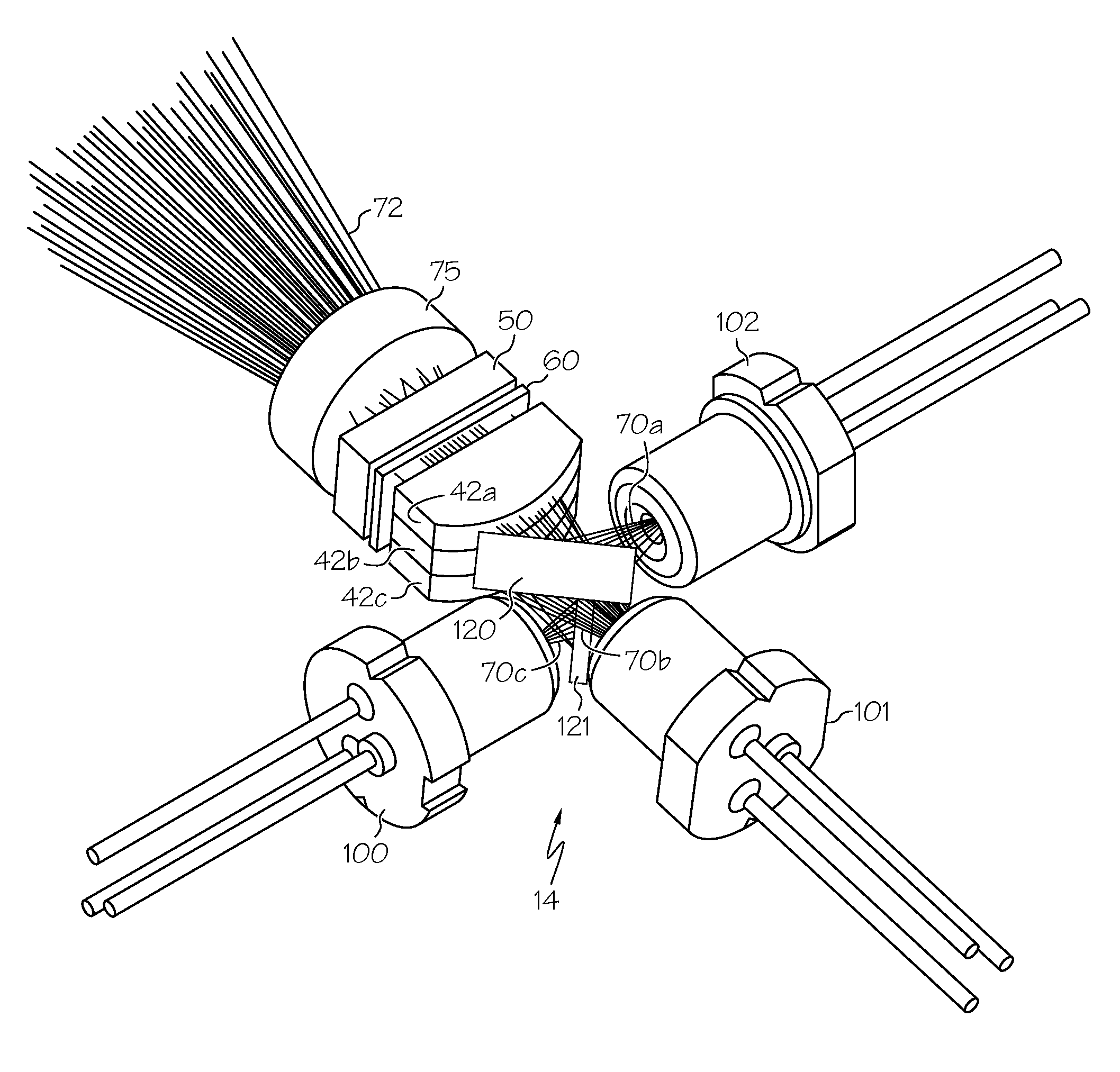
The invention replaces expensive and complex dichroic mirrors with simpler and less expensive broadband mirrors or turning prisms. It also allows for combining multiple lasers with similar or identical wavelengths. Additionally, the invention allows for flexibility in placement of the lasers due to the ability to fold the optical path at compound angles.

Problems solved by technology

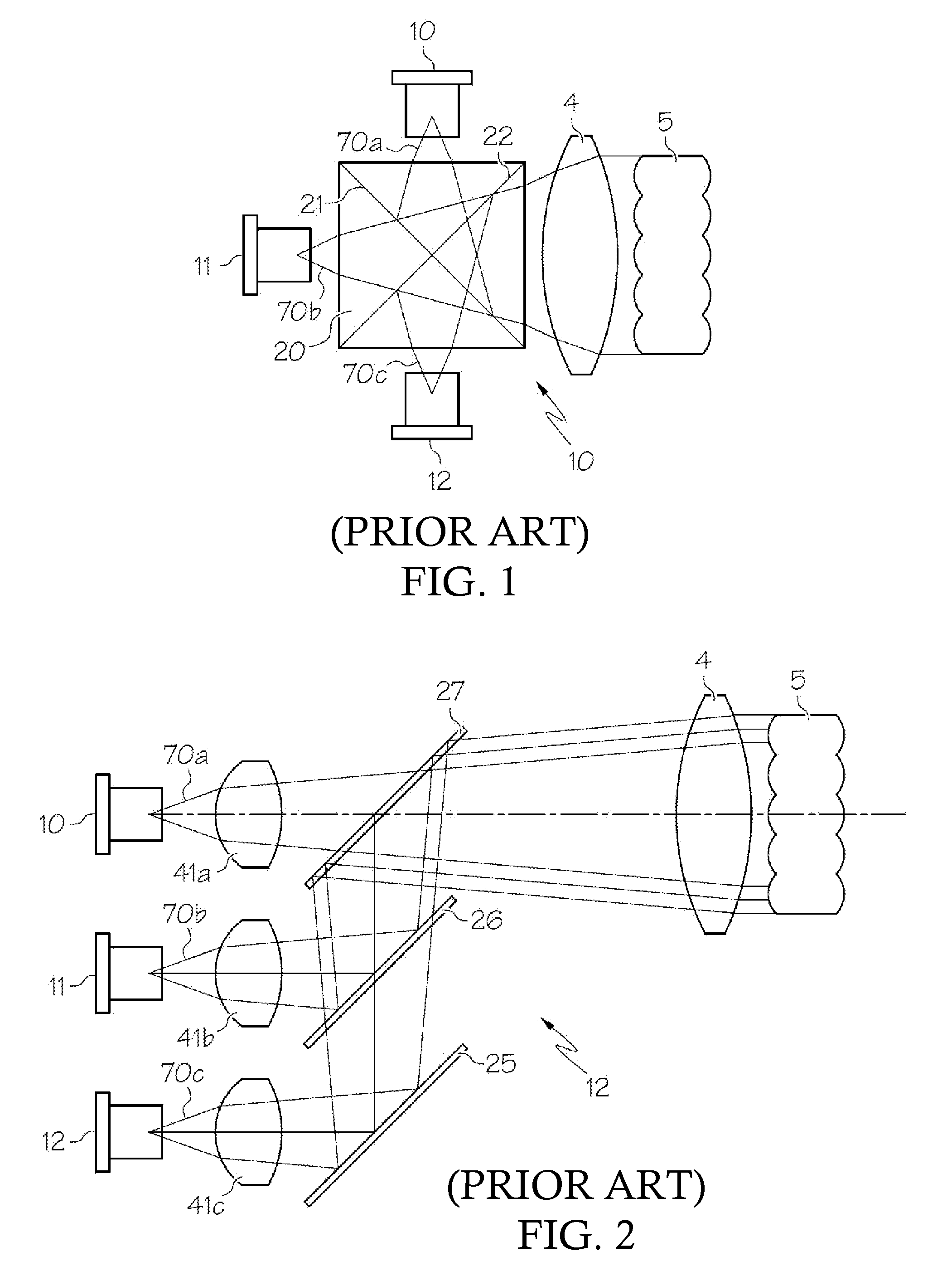
If the right angle prisms are not precisely sharp, then the area at the center (“center seam”) of the “x” where the four (4) prisms join will not function properly, causing loss of light.
The problem of the center seam is more significant as the size of the x-cube decreases.

Method used


Image

  • Projector with laser illumination elements offset along an offset axis
  • Projector with laser illumination elements offset along an offset axis
  • Projector with laser illumination elements offset along an offset axis

Examples


Embodiment Construction

[0025]In the following detailed description of the preferred embodiments, reference is made to the accompanying drawings, which form a part hereof, and in which are shown by way of illustration specific embodiments in which the invention may be practiced. In this regard, directional terminology, such as “top,”“bottom,”“front,”“back,” etc., is used with reference to the orientation of the Figure(s) being described. The components of the present invention can be positioned in a number of different orientations. As such, the directional terminology is used for purposes of illustration and is in no way limiting. On the other hand, the drawings are only schematic and the sizes of components may be exaggerated for clarity. It is to be understood that other embodiments may be utilized and structural changes may be made without departing from the scope of the present invention. Also, it is to be understood that the phraseology and terminology used herein are for the purpose of description a...


PUM


Abstract

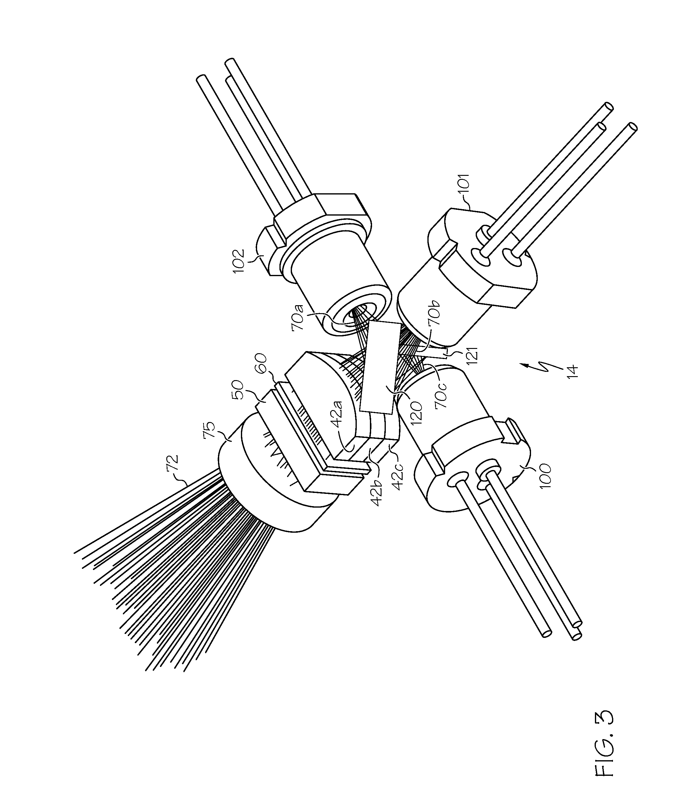
An optical system has projector optics aligned on a projection axis that is orthogonal to an offset axis. A first laser is positioned in a first plane orthogonal to the projection axis. First folding optics are positioned in the first plane to fold a first beam from the first laser to a first portion of the projector optics. A second laser is in a second plane parallel to, and offset along the offset axis from, the first plane. Second folding optics is positioned in the second plane to fold a second beam from the second laser to a second portion of the projector optics to synthesize the first and second beam.

Description

CROSS REFERENCE TO RELATED APPLICATIONS[0001]This application claims the benefit of U.S. Provisional Patent Application 61 / 584,222, entitled “Projector with Laser Illumination” to Rutherford, filed Jan. 7, 2012, the entire contents of which are incorporated herein by reference.BACKGROUND OF THE INVENTION[0002]1. Field of the Invention[0003]The present disclosure relates to projectors with laser light sources. More specifically, the disclosure relates to illumination modules using multiple laser light sources.[0004]2. Description of the Related Art[0005]Projectors can be designed to use several different types of light sources. Larger, higher power projectors typically use arc lamps as the light source. More compact, lower power projectors can use solid state light sources, most commonly light emitting diodes (LEDs) or lasers. Projectors with laser light sources typically use one laser for each color, and the various laser beams are combined using color selective mirrors, known as di...

Claims


Application Information

Patent Timeline
IPC IPC(8): G03B21/14G03B21/20H04N9/31
CPCG03B21/2033H04N9/3161G03B21/2066H04N9/3152G03B21/208G02B27/106G02B27/143G02B27/48G03B21/2013
Inventor RUTHERFORD, TODD S.
Owner GREELIGHT OPTICS
Learn More