Phase-shifted dual-bridge DC/DC converter with wide-range ZVS and zero circulating current

a phase-shifted, dc/dc converter technology, applied in the direction of dc-dc conversion, power conversion systems, instruments, etc., can solve the problems of more voltage ringing across the output rectification device, higher voltage spike, etc., to achieve more voltage ringing, increase voltage spike, and energy-saving

Active Publication Date: 2015-08-25
TEXAS INSTR INC
View PDF16 Cites 21 Cited by
  • Summary
  • Abstract
  • Description
  • Claims
  • Application Information

AI Technical Summary

Benefits of technology

[0016]The embodiments of the primary side circuit are a half-bridge inverter and a full-bridge inverter. For normal operation, the inverters always operate at 50% duty cycle. The magnetizing currents of their power transformers reach a constant and stable peak value at the end of each half switching cycle, assuming there is no magnetic flux walking. When all bridge switches are turned off and commutation starts, the peak magnetizing current and the reflected output current fast charge and discharge the switching devices' parasitic capacitance of both leading and lagging inverters until the voltages across the power transformer windings decreases to zero. After that, the lagging inverter continues its commutation by utilizing its magnetizing energy, while the leading inverter relies on the energy of its power transformer primary leakage inductance. A properly sized magnetizing inductance of a transformer usually can store enough energy for a bridge to achieve ZVS. The lagging inverter can take this advantage and achieve a full-range ZVS. On the other hand, the leading inverter usually needs an extra inductor in addition to transformer primary leakage inductance to store sufficient energy for ZVS operation at light loads. The extra inductor, normally referred to as resonance inductor, is helpful for soft switching, but it could cause a higher voltage spike and more voltage ringing across the output rectification devices. Two series connected diodes may be needed to clamp the node of the power transformer and the resonance inductor connection to positive and negative inputs. While clamping the voltage spike across its power transformer and hence the rectification devices, the circuit also captures most of the transient energy caused by the reverse recovery of rectification devices and minimizes the voltage ringing. Part of the captured energy is dissipated in the power train, but the rest is utilized for ZVS and recycled back to the DC source, and hence the circuit efficiency is improved.
[0017]Unlike a conventional ZVS full bridge converter, the voltage swing rate dv / dt of the lagging inverter's switching devices of this invention is not completely load depended. After the voltage across the power transformer reverses its polarity, there is no secondary reflected current in the transformer primary and the transformer windings are essentially open. Disregarding the small leakage inductance's energy, magnetizing current is the only current to fully charge or discharge bridge switching devices' parasitic capacitances at a much slower voltage swing rate dv / dt to accomplish the ZVS. This circuit characteristic minimizes EMI emission at heavy loads, where most EMI problems occur.

Problems solved by technology

The extra inductor, normally referred to as resonance inductor, is helpful for soft switching, but it could cause a higher voltage spike and more voltage ringing across the output rectification devices.

Method used


Image

  • Phase-shifted dual-bridge DC/DC converter with wide-range ZVS and zero circulating current
  • Phase-shifted dual-bridge DC/DC converter with wide-range ZVS and zero circulating current
  • Phase-shifted dual-bridge DC/DC converter with wide-range ZVS and zero circulating current

Examples


Embodiment Construction

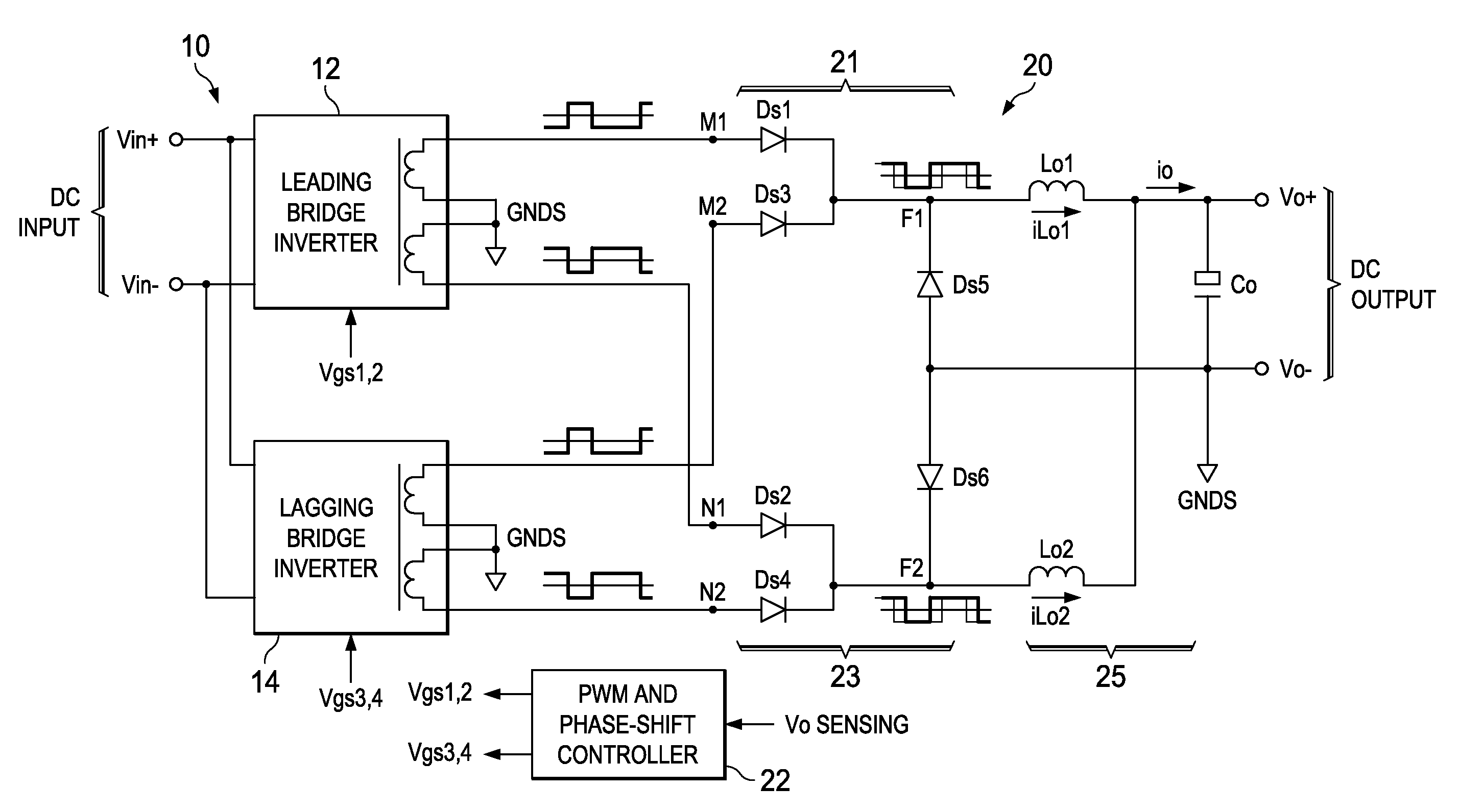
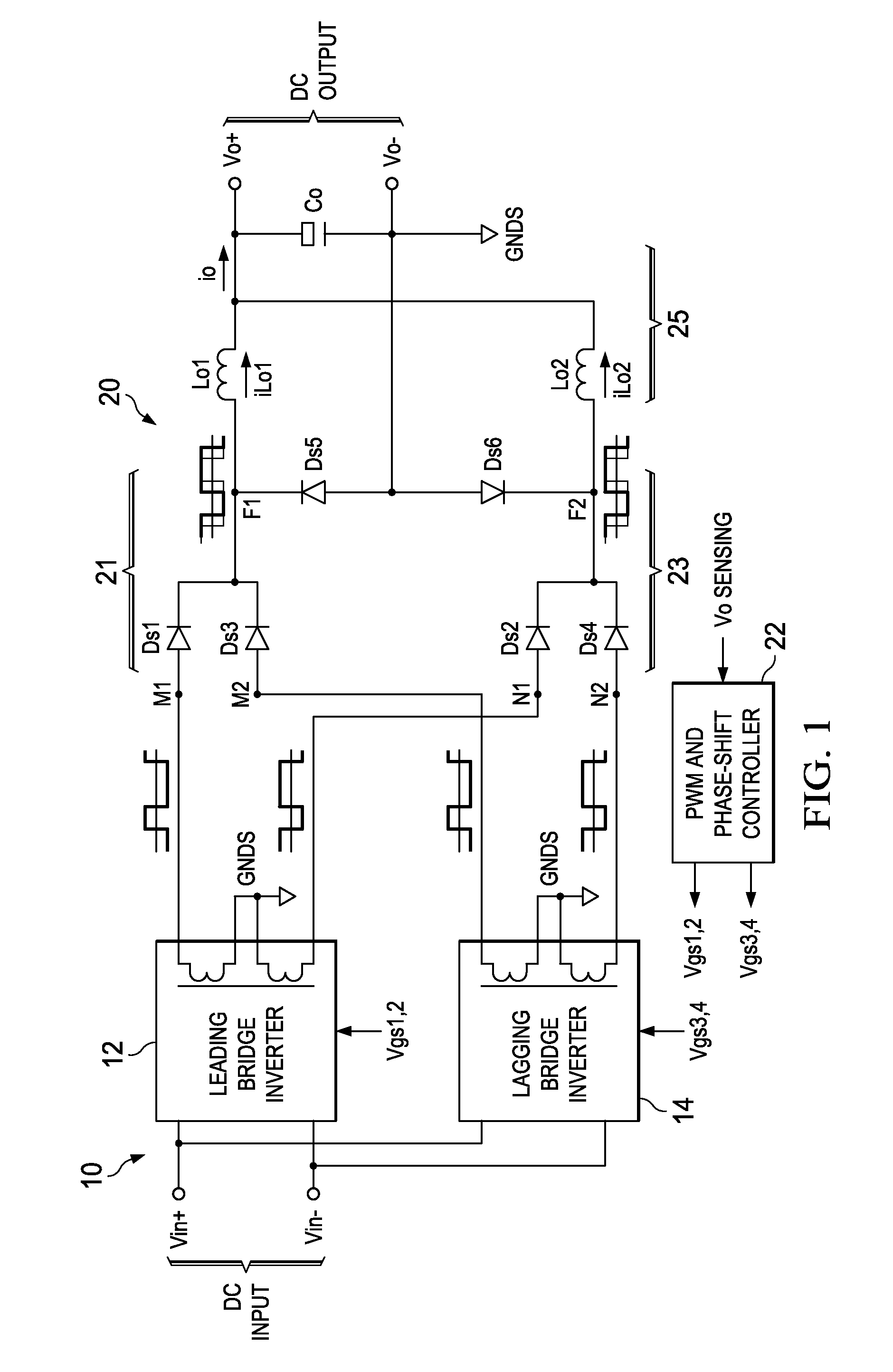
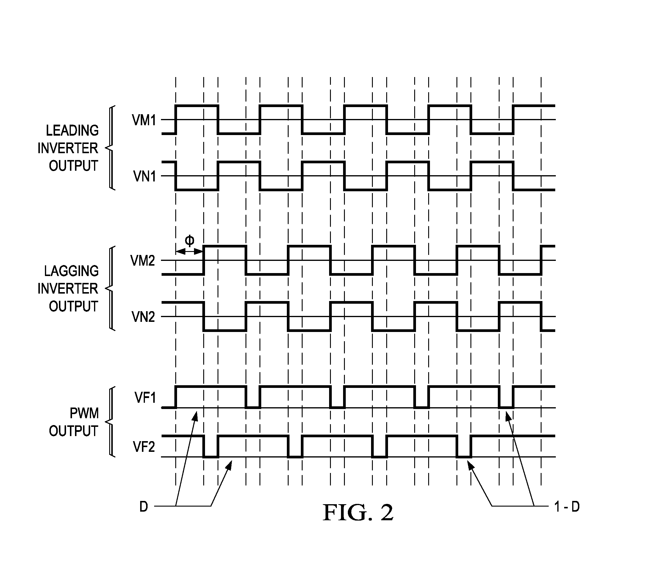
[0034]In the following description, various components and connection nodes will have letter designations and circuit blocks and complicated waveforms will have number designations additionally to make description easier to understand and to simplify the associations between schematic diagrams and waveforms.

[0035]In FIG. 1, illustrated are a DC / DC converter primary 10 comprising bridge inverters 12 and 14, a DC / DC converter secondary 20 comprising two full-wave rectification circuits 21 and 23 and an output filter 25, and a PWM and Phase-Shift controller 22. The phase of the bridge inverter 12 always leads that of the bridge inverter 14 when a phase-shift control is applied to the converter. Because of the phase relationship, the bridge inverter 12 is referred to as Leading Bridge Inverter and the bridge inverter 14 Lagging Bridge Inverter. The converter primary 10 is connected to a DC source by terminals Vin+ and Vin−. Vin+ is the positive input connected to the positive terminal o...


PUM


Abstract

Disclosed is a family of new DC / DC converters and a new control method. The converter comprises two bridge inverters, two full-wave rectification circuits and a current-doubler filter. Each inverter is able to generate a symmetrical and isolated AC output voltage. Phase-shift control is employed to control the phase difference between the two bridge inverters. By shifting the phase, the converter changes the two inverters' output voltage overlapping area to regulate its output voltage. The bridge inverters always operate at 50% duty cycle, like an open loop Bus Converter, to achieve wide-range zero voltage switching and eliminate circulating current for normal operation. For low output voltage regulation and soft start, Pulse Width Modulation (PWM) control is used. The converters and the control method improve power conversion efficiency, maximize magnetic component utilization, reduce semiconductor stress and decrease EMI emission.

Description

CROSS-REFERENCE TO RELATED APPLICATIONS[0001]This application claims the benefit of provisional patent application Ser. No. 61 / 005,163, filed on 2007 Dec. 3 by the present inventor.FEDERALLY SPONSORED RESEARCH[0002]Not ApplicableSEQUENCE LISTING OR PROGRAM[0003]Not ApplicableBACKGROUND OF THE INVENTION[0004]1. Field of Invention[0005]This invention relates in general to power converters and, more specifically, to a dual half-bridge DC / DC converter and a dual full-bridge DC / DC converter with dual power transformers, PWM and Phase-Shift controls and capabilities of wide-range ZVS and zero circulating current.[0006]2. Prior Art[0007]In the field of power conversion, it is a common practice to convert electrical energy from one DC voltage level to the other isolated levels by using high frequency switching technology. The application of switching technology dramatically decreases the size of power converters and improves power conversion efficiency. While enjoying the benefits of switch...

Claims


Application Information

Patent Timeline
Patent Type & Authority Patents(United States)
IPC IPC(8): H02M7/493H02M7/5387H02M3/158
CPCH02M7/53871H02M7/493H02M2003/1586H02M3/1586H02M1/0043
Inventor YE, ZHONG
Owner TEXAS INSTR INC
Why Eureka
Try Eureka