
Battery arrangement and battery mounting structure for a vehicle

a technology for battery mounting and vehicle, which is applied in the direction of cycle equipment, cell components, cell component details, etc., to achieve the effects of prolonging the life of the battery, improving waterproofing, and improving heat generation of electric cells

Active Publication Date: 2006-11-28
HONDA MOTOR CO LTD
View PDF9 Cites 18 Cited by
  • Summary
  • Abstract
  • Description
  • Claims
  • Application Information

AI Technical Summary

Benefits of technology

[0005]The present invention has been conceived in order to solve the above described problems. One object of the present invention is to provide a battery arrangement structure for a vehicle to ensure ample storage space in a storage or luggage box. Another object of the invention is to improve external appearance quality, and to improve battery case layout efficiency and cooling capability.

Problems solved by technology

While, it has been considered to provide a vehicle body cover and to store a battery case inside the vehicle body cover, challenges remain to improve battery case layout efficiency and cooling capability.

Method used


Image

  • Battery arrangement and battery mounting structure for a vehicle
  • Battery arrangement and battery mounting structure for a vehicle
  • Battery arrangement and battery mounting structure for a vehicle

Examples


Embodiment Construction

[0034]Embodiments of the present invention will now be described in the following description with reference being made to the drawings of FIG. 1 to FIG. 13. In the following description, front side refers to the advancing direction of the vehicle, and right side and left side refer to the right side and the left side facing in the advancing direction of the vehicle.

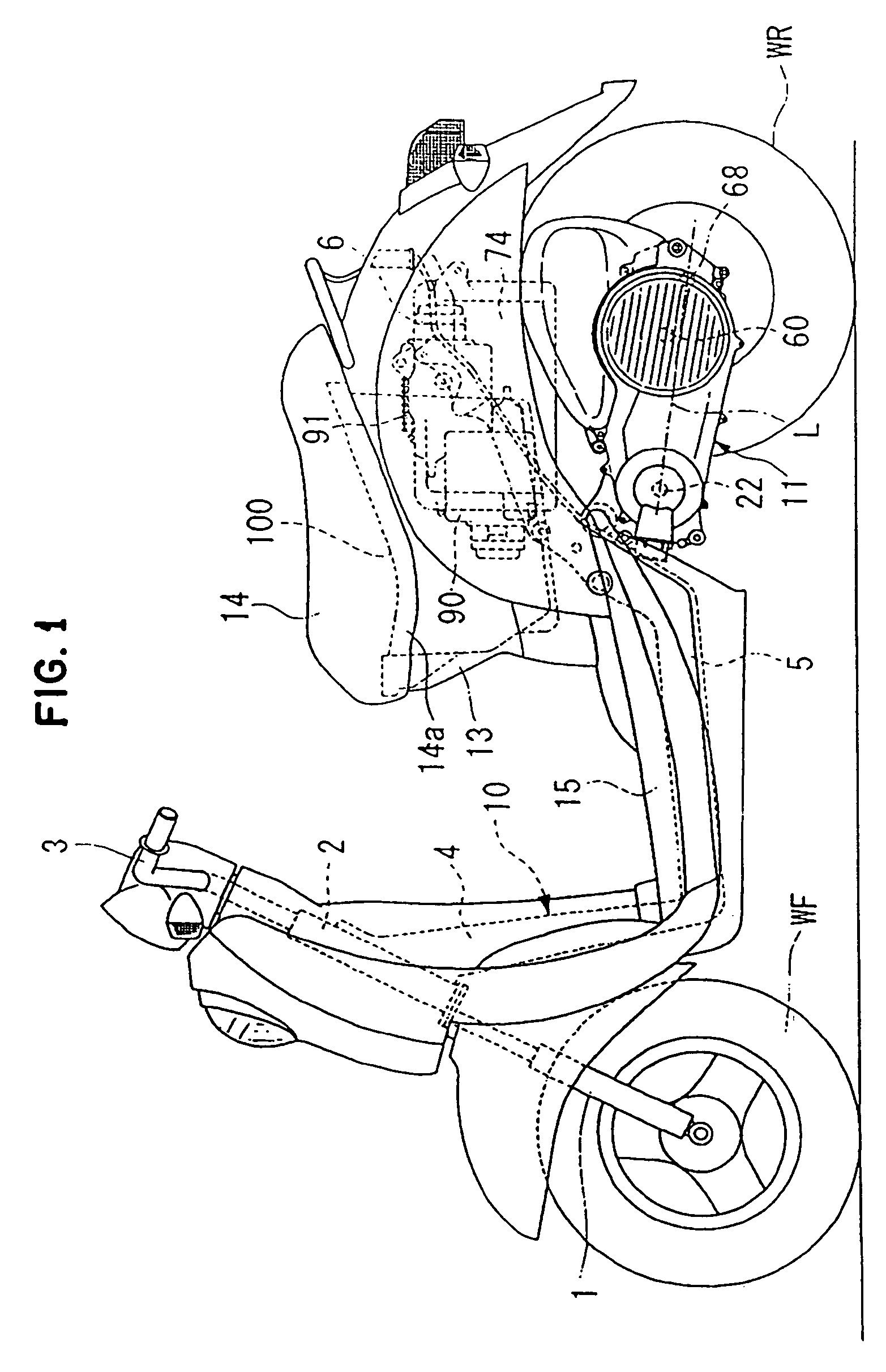
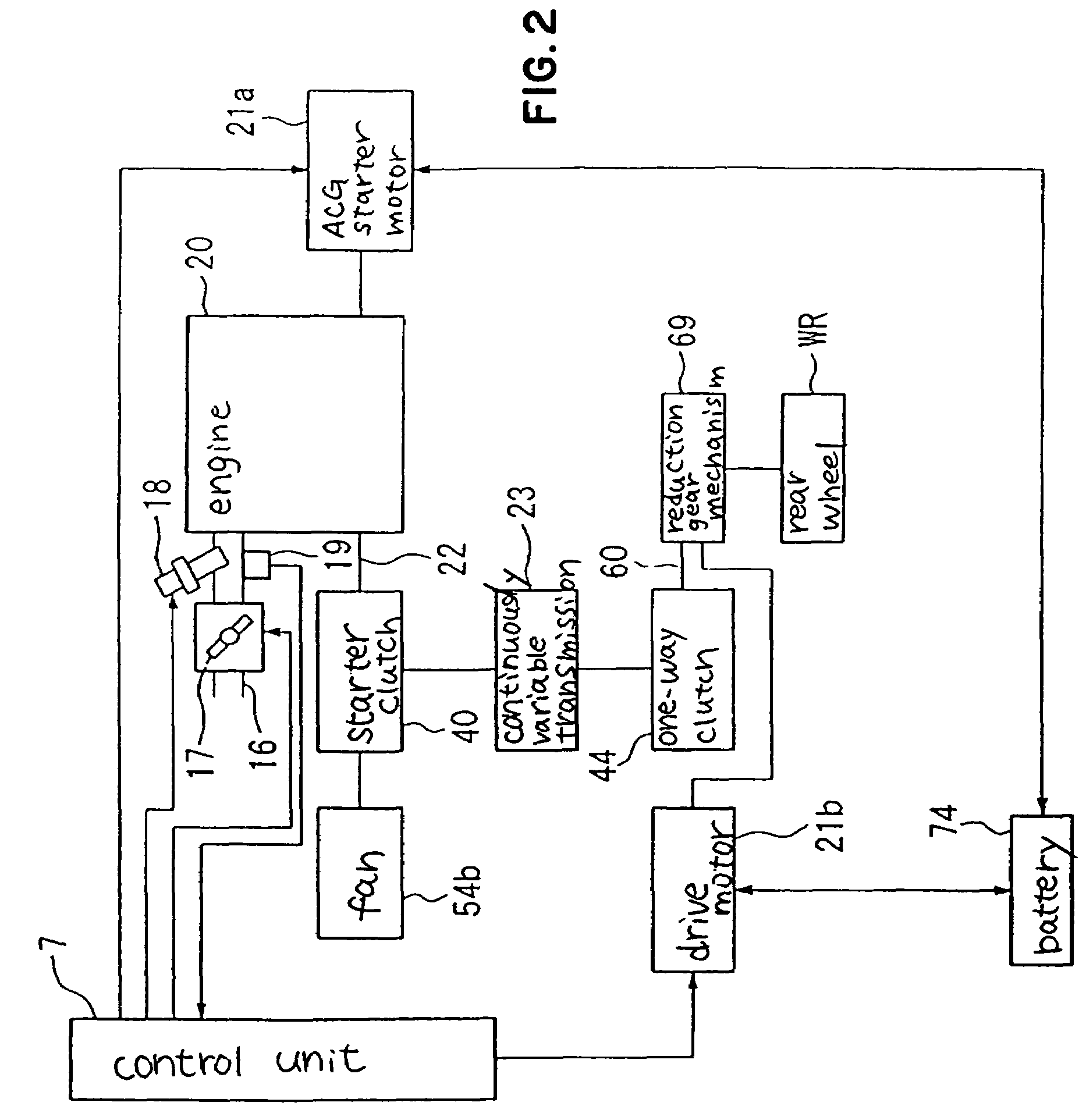
[0035]As shown in FIG. 1, a hybrid vehicle of this embodiment preferably is a unit swing type two-wheeled vehicle, having a vehicle frame 10. The vehicle frame 10 includes a front fork 1 where a front wheel WF is axially supported at the front of the vehicle. The front fork 1 is pivoted on a head pipe 2, and can be steered by operating a handle 3. A downpipe 4 running to the rear and down is attached from the head pipe 2, and a middle frame 5 extends substantially horizontally from a lower end of this downpipe 4. Also, a rear frame 6 is formed running rearwards and upwards from a rear end of the middle frame 5. A power u...


PUM

PropertyMeasurementUnit
forceaaaaaaaaaa
electrical poweraaaaaaaaaa
shapeaaaaaaaaaa

Abstract

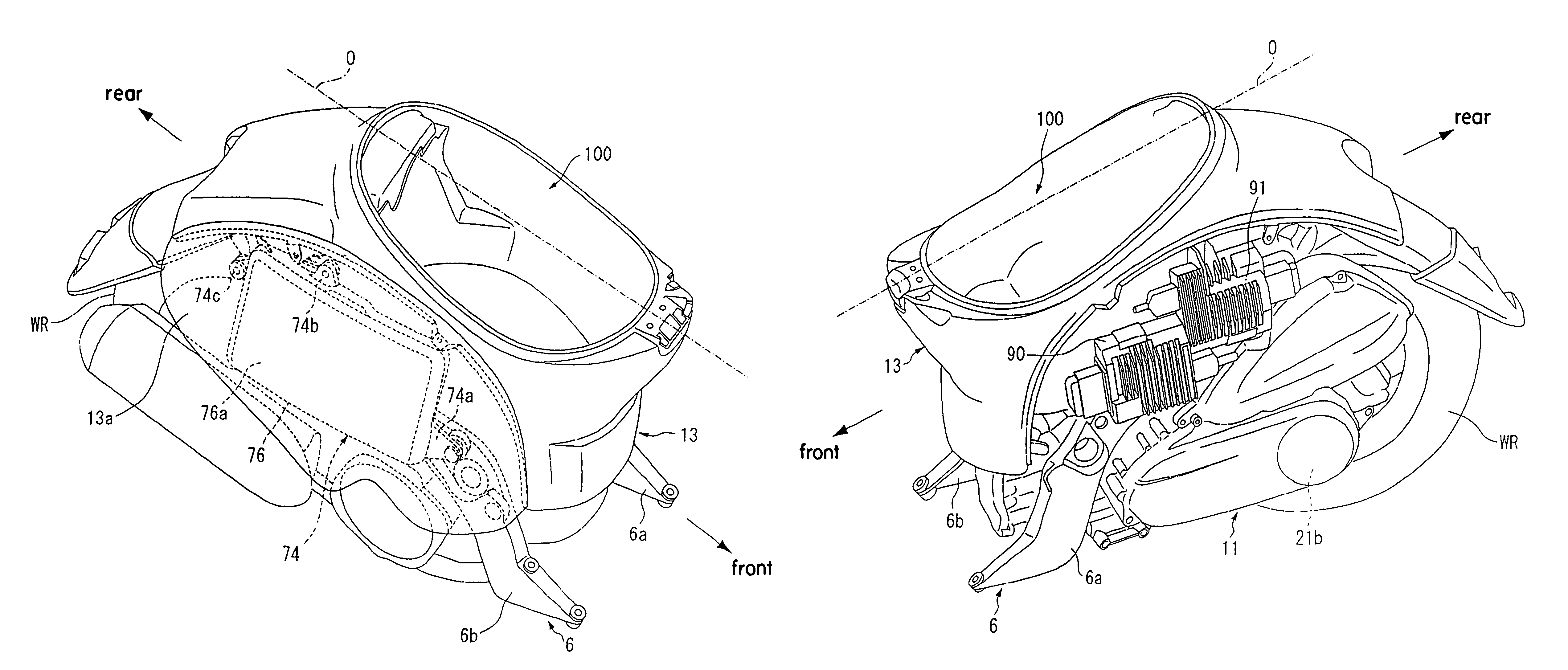
A battery arrangement structure for a vehicle including a motor for transmitting drive force to a drive wheel, a battery for supplying electrical power to the motor, and a storage box. The motor is arranged on one side of a vehicle center line oriented in a longitudinal direction of the vehicle and the battery is arranged on an opposite side of the vehicle center line and around the storage box. A battery mounting structure for a vehicle having a composite battery that includes a plurality of electric cells stored in a battery case, and the battery case being covered from a side cover of an outer side part of a vehicle body cover. The composite battery is formed from a plurality of electrical cells arranged close together in a single row. The battery case includes an outer case half body with an outer shape that runs along an inner surface shape of the side cover.

Description

CROSS REFERENCE TO RELATED APPLICATIONS[0001]This application is based on Japanese patent application nos. JP 2003-338820 and JP 2003-338821.TECHNICAL FIELD OF THE INVENTION[0002]This invention relates to a battery arrangement structure for a vehicle, having at least a motor as a drive power source. This invention relates to a battery mounting structure for a vehicle, including a battery for supplying electrical power to a motor functioning as a drive power source.BACKGROUND OF THE INVENTION[0003]From the related art, as a battery arrangement structure for an electric vehicle, there is known, for example, as disclosed in Japanese patent laid-open No. Hei. 4-358983, a structure with a battery provided beneath a seat, and a motor constituting a drive power source arranged below the battery. With a small two-wheeled vehicle, for example a scooter, it is common for a luggage box for storing a helmet or the like to be provided beneath a seat. However, in this type of two-wheeled vehicle,...

Claims


Application Information

Patent Timeline
Patent Type & Authority Patents(United States)
IPC IPC(8): B60R16/00B60K1/04B62M7/00B62M7/12B62M23/02H01M50/204H01M50/249
CPCB60K1/04B60K6/28B60K6/48B60K6/543B62M7/12H01M2/1077H01M2/1083B60Y2200/126B62K2202/00Y02T10/6221B60Y2200/12Y02T10/62Y02E60/10B62J43/28B62J43/16H01M50/204H01M50/249
Inventor NAKAGAWA, MITSUOTSUKADA, YOSHIAKIONOZAWA, SEIJIARIGA, KYOICHIHORII, YOSHIYUKI
Owner HONDA MOTOR CO LTD
Learn More